After some more farting around with the code, I’ve found that the above sketches more or less work the way I want so I was able to circumvent the need to use Device Selector. Why this is important to me is because I want to interact with the widgets to adjust quantity values only, and rely on the master to post appropriate values to respective devices as needed. It’s nothing that fascinates now, but as I continue to build out my project, I plan to add a small level of autonomy in that I set a flag that initiates a fairly long sequence of events involving several device and several motors/relays per each device. If I needed to continually switch the device selector, the ability to timely perform the tasks would be lost, but by working everything out in code, the sequence would then be able to set into motion in milliseconds. Still much more farting around to do, but I’m at least confident on how to proceed.
I’ve recently included Bridge into my project to control several ESP boards from a single ESP, and all to only use 1 app connected to the master ESP. I have a function that lets me scroll up a value with a Step V widget, and when I tick the button widget, the value is recorded into the master ESP, and also sent to the Bridge1 ESP and that slave ESP toggles a relay for a specified amount of time. That works great and is not my problem.
What I am having problems with is when trying to control the other 7 relays. Some will be controlled by RTC readings, and others by temp/humidity readings. In my previous project I also added in some button widgets to be able to turn the relays back on if they were coded to be off. It is these relays connected to slaveESP that I can’t gain the control of through the Bridge connection. Each time I test a new code edit, I also confirm that the original (semi complex) function works, and it’s good.
For the time being, I’d like to have the master ESP and app toggle the state of a Vpin, and have the slave ESP react to the state of the respective Vpins. Originally, I listed the V pins in the code, then changed to their variable names, and still no go. Here are the 2 sketches so far. I’m seeking assistance in my structuring for the bridge code. Once I know it, I will be further building the master sketch and beginning 2-3 more slave sketches, so I’ll have plenty of practice to sink any new skills.
#define BLYNK_PRINT Serial          // Comment this out to     disable prints and save space
#include <ESP8266WiFi.h>
#include <BlynkSimpleEsp8266.h>
#include <WidgetRTC.h>
#include <TimeLib.h>
#include <DHT.h>
#include <Wire.h>

char auth[] = "masterAUTH";   // Cloud Server


//Initiating Bridge Widget
WidgetBridge Bridge1(V0);   //Relays
WidgetBridge Bridge2(V1);   //Pumps 1-4
WidgetBridge Bridge3(V2);   //Pumps 5-8

BLYNK_CONNECTED() {
  Bridge1.setAuthToken("slaveAUTH1"); // Slave_Relays
  Bridge2.setAuthToken("slaveAUTH2"); // Slave_Pumps 1-4
  Bridge3.setAuthToken("slaveAUTH3"); // Slave_Pumps 5-8
  //Bridge4.setAuthToken("AUTH"); // Slave_XXX
}

char ssid[] = "NetworkName";
char pass[] = "Password";

BlynkTimer timer;
byte blynkInterval = 3000;

WidgetTerminal terminal(V29);
WidgetRTC rtcWidget;            // requires RTC widget in app
DHT dhtA(13, DHT22);            // DHT instance named dhtA, (I/O pin, sensor type)
DHT dhtB(14, DHT22);            // DHT instance named dhtB, (I/O pin, sensor type)

//  DHT Reference Values - CHANGE THESE TO MANAGE YOUR ROOM'S CLIMATE - //
byte hiMaxTemp = 80;   // temp that triggers heat removal device(s) on
byte lowMaxTemp = 70;  // temp that triggers heat removal device(s) off
byte hiMinTemp = 55;   // temp that triggers heater on
byte lowMinTemp = 65;  // temp that triggers heater off
byte hiHum = 50;       // High humidity value that triggers dehumidifier on
byte lowHum = 40; // Low humidity value that triggers dehumidifier off

WidgetLED LEDa(V56);              //lightA Indicator
WidgetLED LEDb(V57);              //lightB Indicator
WidgetLED LEDc(V58);              //VentA Indicator
WidgetLED LEDd(V59);             //VentB Indicator
WidgetLED LEDe(V60);              //scrubberFan Indicator

#define lightA 16             //Relay 1
#define lightB 15             //Relay 2
#define pumpA 14              //Relay 3
#define pumpB 13              //Relay 4
#define ROpump 12             //Relay 5
#define scrubberFan 5        //Relay 6
#define VentA 4              //Relay 7
#define VentB 2              //Relay 8

#define TURN_ON 1 // TURN_ON and TURN_OFF are defined to account for Active LOW relays
#define TURN_OFF 0 // Used to switch relay states for on/off of 120VAC~ devices

int pumpAon;          //Blynk Override to turn pumpA back on
int pumpBon;          //Blynk Override to turn pumpB back on

BLYNK_WRITE(V30) {
  pumpAon = param.asInt();  // pumpA remote
}
BLYNK_WRITE(V31) {
  pumpBon = param.asInt();  // pumpB remote
}

uint32_t msPerGallon = 33000; //ms per gallon
uint32_t ROstart = 0;
uint32_t countGallons;
boolean runningRO = false;
int ROpumpOn = 0;     //Blynk Triggered RO Pump
float totalGallons;   //Number of RO Gallons Selected in Widget

BLYNK_WRITE(V32) {    //V33 Reserved to illuminate button
  ROpumpOn = param.asInt();  // ROpump remote
}
BLYNK_WRITE(V34) {
  totalGallons = param.asFloat();  // ROpump remote
}

//-Digital Pins - Peristaltic Pump Variables - 00 Series Pins
const int pumpPin[8] = { 2, 4, 5, 12, 13, 14, 15, 16 };
int dosingLEDs[8]  = { V40, V41, V42, V43, V44, V45, V46, V47 };
uint32_t multiplier[8] = { 0, 0, 0, 0, 0, 0, 0, 0 }; //ms per ml
uint32_t startPump = 0;
uint32_t runCount;
bool pumpRunning;
const char *nuteType[8] = { "GH Armor Si", "GH Flora Blend", "GH CALiMAGic", "GH Kool Bloom",
                            "GH Flora Gro", "GH Flora Micro", "GH Flora Bloom", "GH pH Down"
                          }; //Text Printed to Terminal Widget^^

float DOSEml;      //Step Widget (0.25 per step, send step/NO, loop values ON)
int button = 0;   //Button Widget set to Switch
int x;           //Correlates Array Positions with Pump Motor Pins
int calibration;

BLYNK_WRITE(V36) {    //X = Pump Select
  x = param.asInt() - 1;
}
BLYNK_WRITE(V37) {
  DOSEml = param.asFloat();
}
BLYNK_WRITE(V38) {    //Pump Start
  button = param.asInt();
}
BLYNK_WRITE(V39) {
  calibration = param.asInt();
}
int AA;
int BB;
int CC;
int DD;
int EE;
int FF;
int GG;

BLYNK_WRITE(V60) {
  AA = param.asInt();  // lightA remote
}
BLYNK_WRITE(V61) {
  BB = param.asInt();  // lightB remote
}
BLYNK_WRITE(V62) {
  CC = param.asInt();  // pumpA remote
}
BLYNK_WRITE(V63) {
  DD = param.asInt();  // pumpB remote
}
BLYNK_WRITE(V65) {
  EE = param.asInt();  // scrubberFan remote
}
BLYNK_WRITE(V66) {
  FF = param.asInt();  // ventA remote
}
BLYNK_WRITE(V67) {
  GG = param.asInt();  // ventB remote
}
//---------------------------------------------------------------//
//----------------------------Functions--------------------------//
void checkBlynk() {
  unsigned long startConnecting = millis();
  unsigned int Timeout = 5000;
  while (!Blynk.connected())
  {
    Blynk.connect();
    if (millis() > startConnecting + Timeout)
    {
      break;
    }
  }
}

void climateRoutine()
{
  byte h1 = dhtA.readHumidity();          // f1 and h1 are fahrenheit and humidity readings
  byte f1 = dhtA.readTemperature(true);   // from DHT/A
  byte h2 = dhtB.readHumidity();          // f2 and h2 are fahrenheit and humidity readings
  byte f2 = dhtB.readTemperature(true);   // from DHT/B
  if (isnan(f1) || isnan(f2) || isnan(h1) || isnan(h2)) {
    terminal.println("Failed to read from a DHT sensor");
    terminal.flush();
    return;
  }
  Blynk.virtualWrite(V10, f1);      //  Set Virtual Pin 0 frequency to PUSH in Blynk app
  Blynk.virtualWrite(V11, h1);      //  Set Virtual Pin 1 frequency to PUSH in Blynk app
  Blynk.virtualWrite(V12, f2);      //  Set Virtual Pin 2 frequency to PUSH in Blynk app
  Blynk.virtualWrite(V13, h2);      //  Set Virtual Pin 3 frequency to PUSH in Blynk app
  //-------------------Bloom A Temp Test---------------------------------------//
  bool F1;
  if (f1 >= hiMaxTemp)
  {
    Bridge1.virtualWrite(FF, TURN_ON);
    if (F1)
    {
      F1 = false;
      terminal.println("Exhausting the heat from Bloom A"); //  Text printed to terminal monitor
    }
  }
  else if (f1 <= lowMaxTemp)
  {
    F1 = true;
    Bridge1.virtualWrite(FF, TURN_OFF);
  }
  //-----------------------Bloom A Humidity Test-------------------------//
  bool H1;
  if (h1 >= hiHum)
  {
    Bridge1.virtualWrite(FF, TURN_ON);
    if (H1)
    {
      H1 = false;
      terminal.println("Exhausting the RH from Bloom A");
    }
  }
  else if (h1 <= lowHum)
  {
    H1 = true;
    Bridge1.virtualWrite(FF, TURN_OFF);
  }
  //-----------------------Bloom B Temp Test-----------------------------//
  bool F2;
  if (f2 >= hiMaxTemp)
  {
    Bridge1.virtualWrite(GG, TURN_ON);
    if (F2)
    {
      F2 = false;
      terminal.println("Exhausting the heat from Bloom B");
    }
  }
  else if (f2 <= lowMaxTemp)
  {
    F2 = true;
    Bridge1.virtualWrite(GG, TURN_OFF);
  }
  //-----------------------Bloom B Humidity Test-------------------------//
  bool H2;
  if (h2 >= hiHum)
  {
    Bridge1.virtualWrite(GG, TURN_ON);
    if (H2)
    {
      H2 = false;
      terminal.println("Exhausting the RH from Bloom B");
    }
  }
  else if (h2 <= lowHum)
  {
    H2 = true;
    Bridge1.virtualWrite(GG, TURN_OFF);
  }
  terminal.flush();
}

void displayDateTime()
{
  byte HOUR = hour();
  byte twelveHour = hour() - 12; // Variable used to display 13+ hours in 12 hour format
  byte zeroHour = 12;                // Variable use to convert "0" zero hour to display it as 12:00+
  byte displayHour;
  byte MIN = minute();
  byte SEC = second();
  char* meridian;

  if (hour() == 0)  // First we test if the hour reads "0"
  {
    displayHour = zeroHour;
    meridian = "AM";
  }
  else if (hour() >= 13)  // if no, Second we test if the hour reads "13 or more"
  {
    displayHour = twelveHour;
    meridian = "PM";
  }
  else
  {
    displayHour = hour();
    meridian = "AM";
  }
  if (Blynk.connected())
  {
    char Clock[16];
    char Date[16];
    sprintf(Clock, "%02d:%02d:%02d-%02s", displayHour, MIN, SEC, meridian);
    sprintf(Date, "%02d/%02d/%04d", month(), day(), year());
    Blynk.virtualWrite(V26, Clock);      //  Set Value Display frequency to PUSH in Blynk app
    Blynk.virtualWrite(V27, Date);      //  Set Value Display frequency to PUSH in Blynk app
  }
}
void timeRoutine()
{
  //------------------12/12 BloomA Light - 5AM-5PM
  //Adjust hours and minutes in accordance with 24 hour time format.
  //Create tests where true is ON time and false is OFF time.
  boolean lightAstate = false;
  bool Aon;
  if (hour() >= 5 && hour() <= 16) lightAstate = true;
  if (lightAstate == true)
  {
    Bridge1.virtualWrite(AA, TURN_ON);
    if (Aon)
    {
      Aon = false;
      terminal.println("Lights On In Bloom A");  //  Text printed to terminal monitor
    }
  }
  else
  {
    Aon = true;
    Bridge1.virtualWrite(AA, TURN_OFF);
  }

  //--------------------12/12 Bloom B Light - 5PM-5AM
  //lightB is lit during the opposing 12 hours to lightA to conserve current draw from HID ballasts.
  boolean lightBstate = false;
  bool Bon;
  if (lightAstate == false) lightBstate = true;
  if (lightBstate == true)
  {
    Bridge1.virtualWrite(BB, TURN_ON);
    if (Bon)
    {
      Bon = false;
      terminal.println("Lights On In Bloom B");  //  Text printed to terminal monitor
    }
  }
  else
  {
    Bon = true;
    Bridge1.digitalWrite(BB, TURN_OFF);
    Blynk.virtualWrite(V57, 0);
  }
  //---------------Bloom A Feed Times------------------------
  boolean pumpAstate = false;
  bool Arun;
  if (pumpAon == 1) pumpAstate = true;
  if (hour() == 6 && minute() >= 0 && minute() < 10) pumpAstate = true;    //6:00 am - 10 mins
  if (hour() == 8 && minute() >= 30 && minute() < 40) pumpAstate = true;  //8:30 am - 10 mins
  if (hour() == 11 && minute() >= 00 && minute() < 10) pumpAstate = true;  //11:00 am - 10 mins
  if (hour() == 13 && minute() >= 30 && minute() < 40) pumpAstate = true;  //1:30 pm - 10 mins
  if (hour() == 16 && minute() >= 0 && minute() < 10) pumpAstate = true;  //4:00 pm - 10 mins
  if (pumpAstate == true)
  {
    Blynk.virtualWrite(V30, 1);
    Bridge1.virtualWrite(CC, TURN_ON);
    if (Arun)
    {
      Arun = false;
      terminal.println("Pump A Is On");  //  Text printed to terminal monitor
    }
  }
  else
  {
    Arun = true;
    pumpAon = 0;
    Blynk.virtualWrite(V30, 0);
    Bridge1.virtualWrite(CC, TURN_OFF);
  }
  //---------------------------Bloom B Feed Times-------------------------------------
  boolean pumpBstate = false;
  bool Brun;
  if (pumpBon == 1) pumpBstate = true;
  if (hour() == 18 && minute() >= 0 && minute() < 10) pumpBstate = true;     //6:00 pm - 10 mins -//- 1 hour after light on
  if (hour() == 20 && minute() >= 30 && minute() < 40) pumpBstate = true;   //8:30 pm - 10 mins
  if (hour() == 23 && minute() >= 0 && minute() < 10) pumpBstate = true;     //11:00 pm - 10 mins
  if (hour() == 1 && minute() >= 30 && minute() < 40) pumpBstate = true;    //1:30 am - 10 mins
  if (hour() == 4 && minute() >= 0 && minute() < 10) pumpBstate = true;     //4:00 am - 10 mins
  if (pumpBstate == true)
  {
    Blynk.virtualWrite(V31, 1);
    Bridge1.virtualWrite(DD, TURN_ON);
    if (Brun)
    {
      Brun = false;
      terminal.println("Pump B Is On");  //  Text printed to terminal monitor
    }
  }
  else
  {
    Brun = true;
    pumpBon = 0;
    Blynk.virtualWrite(V31, 0);
    Bridge1.virtualWrite(DD, TURN_OFF);
  }
  terminal.flush();
}

void ROcheck()  //RO Pump = 34 seconds on time per gallon
{
  if (ROpumpOn == 1 && runningRO == false)            // Activates when Blynk button is toggled
  {
    Bridge1.virtualWrite(V64, totalGallons);
    terminal.print("Pumping:");
    terminal.print(totalGallons);
    terminal.println(" Gallons of RO");
    Blynk.virtualWrite(V33, 1);                     // Illuminates Blynk button widget
    runningRO = true;
    ROstart = millis();
    countGallons = msPerGallon * totalGallons;        // Calculates length of runtime for
    Blynk.virtualWrite(V34, 0);
  }
  if (millis() - ROstart > countGallons)              // Determines when runtime ends
  {
    ROpumpOn = 0;
    runningRO = false;
    Blynk.virtualWrite(V32, 0);                 // Turn off lit button widget
    Blynk.virtualWrite(V33, 0);                 // Turn off lit button widget
  }
  terminal.flush();
}

void dosingPumps()
{
  /*  #define bridgeX = Bridge2;
    if ([x] <= 3) {
      bridgeX = Bridge1;
    }
    else() {
      bridgeX = Bridge2;
    }*/
  if (button == 1 && pumpRunning == false)
  {
    multiplier[x] = calibration;                      // Gets the value in [x] position from Blynk
    Blynk.virtualWrite(V36, 0);
    Blynk.virtualWrite(V37, 0);
    Blynk.virtualWrite(V38, 0);                        // Keeps button ON until fully executed
    pumpRunning = true;
    Bridge2.digitalWrite(pumpPin[x], HIGH);
    Blynk.virtualWrite(dosingLEDs[x], 255);           // [x] position Blynk indicator LED
    startPump = millis();
    runCount = DOSEml * multiplier[x];
    terminal.print("Dosing in: ");
    terminal.print(DOSEml);
    terminal.print(" milliliters of ");
    terminal.println(nuteType[x]);
  }
  if (millis() - startPump > runCount)
  {
    Bridge2.digitalWrite(pumpPin[x], LOW);
    Blynk.virtualWrite(dosingLEDs[x], 0);
    pumpRunning = false;
    button = 0;
  }
  terminal.flush();
}

//------------------------Functions------------------------------//
//---------------------------------------------------------------//

void setup()
{
  Serial.begin(115200);
  Wire.begin(SDA, SCL);                                   //Configures I2C for ESP8266
  Blynk.begin(auth, ssid, pass, "blynk-cloud.com", 8442); // Cloud Server
  //Blynk.begin(auth, ssid, pass, server_ip, 8442);       // Local Server
  WiFi.begin(ssid, pass);
  Blynk.config(auth);
  dhtA.begin();
  dhtB.begin();
  rtcWidget.begin();

  pinMode(13, INPUT_PULLUP);    // DHT22 use internal pullup resistors
  pinMode(14, INPUT_PULLUP);    // DHT22 use internal pullup resistors

  timer.setInterval(2002L, timeRoutine);         // 2 second intervals between timed routiness
  timer.setInterval(5001L, climateRoutine);      // 5 second intervals between climate routines
  timer.setInterval(1000L, displayDateTime);     // update the LCD Widget every 5 seconds
  //timer.setInterval(2007L, dosingPumps);         // 0.2 second interval to maintain accuracy (+/- .25)
  timer.setInterval(2003L, ROcheck);             // 1 second interval between RO pump routines
  timer.setInterval(blynkInterval, checkBlynk);  // check connection to server per blynkInterval

  //while (Blynk.connect() == false) {}

  for (int VV = 0; VV < 100; VV++) {   //Vpins 0-50 defaulted to zero
    Blynk.virtualWrite(VV, 0);
  }
  terminal.flush();
  delay(1000);
  Serial.println("setup complete.");
}

void loop()
{
  // only attempt Blynk-related functions when connected to Blynk
  if (Blynk.connected())
  {
    Blynk.run();
  }
  timer.run();
}
Slave Sketch
//------------SLAVE RELAYS

#define BLYNK_PRINT Serial          // Comment this out to     disable prints and save space
#include <ESP8266WiFi.h>
#include <BlynkSimpleEsp8266.h>

char auth[] = "slaveAUTH1";   // Cloud Server

char ssid[] = "NetworkName";
char pass[] = "Password";

//Initiating Bridge Widget
WidgetBridge Bridge1(V0);   //Relays
BlynkTimer timer;
byte blynkInterval = 3000;

uint32_t msPerGallon = 33000; //ms per gallon
uint32_t ROstart = 0;
uint32_t countGallons;
boolean runningRO = false;
float totalGallons;   //Number of RO Gallons Selected in Widget

int lightA = 16;             //Relay 1
int lightB = 15;             //Relay 2
int pumpA = 14;              //Relay 3
int pumpB = 13;              //Relay 4
int ROpump = 12;             //Relay 5
int scrubberFan = 5;         //Relay 6
int ventA = 4;               //Relay 7
int ventB = 2;               //Relay 8

int AA; //lightA vPIN
int BB; //lightB vPIN
int CC; //pumpA vPIN
int DD; //pumpB vPIN
int EE; //scrubberFan vPIN
int FF; //ventA vPIN
int GG; //ventB vPIN

#define TURN_ON LOW // TURN_ON and TURN_OFF are defined to account for Active LOW relays
#define TURN_OFF HIGH // Used to switch relay states for on/off of 120VAC~ devices

BLYNK_WRITE(V60) {
  AA = param.asInt();  // lightA remote
}
BLYNK_WRITE(V61) {
  BB = param.asInt();  // lightB remote
}
BLYNK_WRITE(V62) {
  CC = param.asInt();  // pumpA remote
}
BLYNK_WRITE(V63) {
  DD = param.asInt();  // pumpB remote
}
BLYNK_WRITE(V64) {
  totalGallons = param.asFloat();  // ROpump remote
}
BLYNK_WRITE(V65) {
  EE = param.asInt();  // scrubberFan remote
}
BLYNK_WRITE(V66) {
  FF = param.asInt();  // ventA remote
}
BLYNK_WRITE(V67) {
  GG = param.asInt();  // ventB remote
}

//---------------------------------------------------------------//
//----------------------------Functions--------------------------//
void checkBlynk() {
  unsigned long startConnecting = millis();
  unsigned int Timeout = 5000;
  while (!Blynk.connected())
  {
    Blynk.connect();
    if (millis() > startConnecting + Timeout)
    {
      break;
    }
  }
}

void ROcheck()  //RO Pump = 34 seconds on time per gallon
{
  if (totalGallons > 0 && runningRO == false)            // Activates when Blynk button is toggled
  {
    Serial.print(totalGallons);
    Serial.println(" - Gallons");
    digitalWrite(ROpump, TURN_ON);
    runningRO = true;
    ROstart = millis();
    countGallons = msPerGallon * totalGallons;        // Calculates length of runtime for pump
  }
  if (millis() - ROstart > countGallons)              // Determines when runtime ends
  {
    Blynk.virtualWrite(V64, 0);
    totalGallons = 0;
    digitalWrite(ROpump, TURN_OFF);
    runningRO = false;
  }
}

void relayCommands()
{
  if (AA == 1){
    digitalWrite(lightA, TURN_ON);
  }
  else if (AA == 0){
    digitalWrite(lightA, TURN_OFF);
  }
  if (BB == 1){
    digitalWrite(lightB, TURN_ON);
  }
  else if (BB == 0){
    digitalWrite(lightB, TURN_OFF);
  }
  if (CC == 1){
    digitalWrite(pumpA, TURN_ON);
  }
  else if (CC == 0){
    digitalWrite(pumpA, TURN_OFF);
  }
  if (DD == 1){
    digitalWrite(pumpB, TURN_ON);
  }
  else if (DD == 0){
    digitalWrite(pumpB, TURN_OFF);
  }
  /*if (V64 == 1){
    digitalWrite(ROpump, TURN_ON);
  }
  else {
    digitalWrite(ROpump, TURN_OFF);
  }*/
  if (EE == 1){
    digitalWrite(scrubberFan, TURN_ON);
  }
  else if (EE == 0){
    digitalWrite(scrubberFan, TURN_OFF);
  }
  if (FF == 1){
    digitalWrite(ventA, TURN_ON);
  }
  else if (FF == 0){
    digitalWrite(ventA, TURN_OFF);
  }
  if (GG == 1){
    digitalWrite(ventB, TURN_ON);
  }
  else if (GG == 0){
    digitalWrite(ventB, TURN_OFF);
  }
}

//------------------------Functions------------------------------//
//---------------------------------------------------------------//

void setup()
{
  Serial.begin(115200);
  Blynk.begin(auth, ssid, pass, "blynk-cloud.com", 8442); // Cloud Server
  //Blynk.begin(auth, ssid, pass, server_ip, 8442);       // Local Server
  WiFi.begin(ssid, pass);
  Blynk.config(auth);

  pinMode(lightA, OUTPUT);
  pinMode(lightB, OUTPUT);
  pinMode(pumpA, OUTPUT);
  pinMode(pumpB, OUTPUT);
  pinMode(ROpump, OUTPUT);
  pinMode(scrubberFan, OUTPUT);
  pinMode(ventA, OUTPUT);
  pinMode(ventB, OUTPUT);

  digitalWrite(lightA, TURN_OFF);
  digitalWrite(lightB, TURN_OFF);
  digitalWrite(pumpA, TURN_OFF);
  digitalWrite(pumpB, TURN_OFF);
  digitalWrite(ROpump, TURN_OFF);
  digitalWrite(scrubberFan, TURN_OFF);
  digitalWrite(ventA, TURN_OFF);
  digitalWrite(ventB, TURN_OFF);

  timer.setInterval(250L, relayCommands);          // 25 second intervals between timed routiness
  timer.setInterval(201L, ROcheck);                  // .2 second interval between RO pump routines
  timer.setInterval(blynkInterval, checkBlynk);    // check connection to server per blynkInterval

  //while (Blynk.connect() == false) {}

  for (int VV = 0; VV < 100; VV++) {   //Vpins 0-50 defaulted to zero
    Blynk.virtualWrite(VV, 0);
  }
  delay(1000);
  Serial.println("setup complete.");
}

void loop()
{
  // only attempt Blynk-related functions when connected to Blynk
  if (Blynk.connected())
  {
    Blynk.run();
  }
  timer.run();
}
The function that DOES work well is called ROcheck. It controls a water pump connected to the relay and metes out 0.25-10.00 gallons of water, though the volume and frequency can easily be changed in the app setup. Once I learn the syntax of how to control the relays, I will work to flesh out my project more as I’d ultimately like to be able to send respective sensor readings from device to device so to allow the recipient to have enough information to process to execute a task in the event the comm link is severed. For now, I just want to get over this hurdle and gain the ability to turn things on or off over the bridge.
Funny thing: I’m currently doing roughly the same thing as you. My setup is
thermostat<–>central<–>relay
where central also communicates with the app.
Anyway I had a look at your code and couldn’t quite make sense of it, but its probably related to you not yet getting the syntax.
It took me a while to get use to it but essentially it boils down to:
- create a channel from device MASTER to SLAVE. You do this in the code of MASTER. As far as i can see you did that:
WidgetBridge Bridge1(V0); //Relays
BLYNK_CONNECTED() {
Bridge1.setAuthToken(“slaveAUTH1”); // Slave_Relays
etc. - Sending anything from MASTER to SLAVE goes over channel V0, so best to NOT use it for anything else.
- You can now use (in MASTER code)
Bridge1.digitalwrite to directly update a physical pin or
Bridge1.virtualWrite to update a virtual pin on SLAVE. Lets assume you do the latter and update V2 - then on SLAVE you need an ‘event handler’ for V2 which is
BLYNK_WRITE(V2) {
//this code is activated as soon as V2 is remotely changed by MASTER
//retrieving any send value or values over V2 is done with:
value = param.asInt();
}
That’s it. Communication the other way round is also possible but then you have to open up a channel on SLAVE as well (to master) and basically the same applies as i’ve just described.
Thanks for the reply @wolph42 . As best as I can tell, my sketches adhere to your instructions. V0 is for the bridge itself and is never referred to again. I’m using V60-V67 with V64 reserved as a float() for th ROcheck() function. The rest are ints. I generically named then in sequence AA-GG, skipping V64. To cover my bets, I duplicated the Vpin reference in both sketches. In master sketch
BLYNK_WRITE(V60) {
  AA = param.asInt();  // lightA remote
}
if (test == true)
{
  Bridge1.virtualWrite(AA = 1);
}
and in slave sketch
BLYNK_WRITE(V60) {
  AA = param.asInt();  // lightA remote
}
if (AA == 1)
{
  digitalWrite(pin, TURN_ON);
}
Assuming the above relationship generates a value of 1, puts it into int AA, sends that over Bridge1 in the AA vPin of V60, the slave should adjust the slaves digital pin accordingly, correct?
Why not simply use this…
BLYNK_WRITE(V60) {
  AA = param.asInt();  // lightA remote
}
if (test == true)
{
  Bridge1.digitalWrite(pin, TURN_ON);
Although the variable TURN_ON might not be recognized by the sending sketch… so just use HIGH (or LOW if inverse triggered)
Bridge is just a way of having your Transmitting device’s sketch “push buttons, adjust sliders, send data, etc.” as if it was you doing so from the Receiving devices’ App project.
Using digitalWrite would likely solve my immediate problem, but that approach will soon fail once I embark on rewriting my functions to pass sensor data to another device w/o sensors. In that situation, I will need to know how to have the recipient behave differently depending on the data value at the time. I’ll switch them to digitalWrite now and try to work my way back towards virtualWrite from a functional sketch. I’m just perplexed because I can pass a float to device B, and device B responds correctly. But when it comes to the ints, it’s like it’s clueless, lol.
I believe most virtual pin data is processed as strings anyhow, it is the param.asXYZ() that determines the final format as int, float, etc.
erm no. Well it depends on the rest of your code obviously but it doesn’t look like it.
Im assuming that the ‘master’ blynk_write(V60) receives its value from the app. So from then on AA contains whatever value the app send.
Now basically you can directly push that value onwards to the slave and I personally would do that from withing the master blynk_write functions. So:
BLYNK_WRITE(V60) { //receive from app
  AA = param.asInt();  // lightA remote
  Bridge1.virtualWrite(V60, AA); //send to slave
}
and as you can see you made another mistake, with virtual write you first give the pin and then the value. This:
Bridge1.virtualWrite(AA = 1);
is a syntax error.
Btw: it also helps if you comment your code especially with the send and receive sections, partially for yourself so you understand whats going on in a year from now and partially for on this forum so its clear to use what your intent with the code is. I’ve added some comment as example.
as for floats vs ints vs strings, @Gunner already answered that param.asXXX();
Thanks for the replies. I’ve been building my sketch/project for about 3 years now and in that time I’ve learned a bunch. Initially I had to code very well commented, but due to millions of edits, copy/pasting, reformatting etc, I found many of the comments no longer applied, so I was in the process of deleting them, and once I iron out this issue, I will clean up my functions accordingly, then proceed to re-add well described comments. So sorry, for the added confusions due to that.
I’ve tried several different combinations of the suggested use of BLYNK_WRITE, though I’ve found it can’t be used inside of a parent function. Or perhaps it just needs to be duplicated into the respective function, I’m still trying different things.
To further confound this issue, I tried running a Blink sketch to verify that my relay modules work with the ESP and the first relay module was only able to trigger 3 of the 8 relays. Thinking my module might be bad, I changed it out for a new unused module and 0 of the 8 will toggle. Someone suggested to no longer use pin 0, but I’ve already corrected that by using pins 2-4-5-12-13-14-15-16. I’ve had some code attempts that managed to light up the LED per each channel of the module, but the relays themselves don’t seem to want to toggle.
As it relates to your suggested usage of BLYNK_WRITE, how would you infuse the correct language into this random function test that reads a DHT temperature in Fahrenheit (f1) and sends a call to device B to trigger the respective digital pin?
TURN_ON = 1
TURN_OFF = 0
//Declarations
BLYNK_WRITE(V66) {
  FF = param.asInt();  // ventA remote
  Bridge1.virtualWrite(V66, FF); //send to slave
}
//End of Declarations

//Inside a function
  if (f1 >= hiMaxTemp)
  {
    Bridge1.virtualWrite(V66, TURN_ON);
    if (F1)
    {
      F1 = false;
      terminal.println("Exhausting the heat from Bloom A"); //  Text printed to terminal monitor
    }
  }
  else if (f1 <= lowMaxTemp)
  {
    F1 = true;
    Bridge1.virtualWrite(V66, TURN_OFF);
  }
I need more information. Whats your setup in this? What is the master and what the slave, apparently im looking at the code from the ‘master’? Then this:
makes little sense. Reading it it says: when master receives input from slave? app? on V66 then send that value to slave?
and then later one you again send an new value TURN_ON or OFF on the same pin V66, to the same slave depending on some variables.
‘BLYNK_WITE(V66)’ literally means: in the event that this device (where this code is running) receives a value on V66 THEN execute the code in this routine. In this case: pass that value on to the slave. And indeed you cannot ‘hide’ that code inside a class or other routine. It has to be outside any routine.
The terms “Master and Slave” for Bridge are a bit of a misnomer… more correctly would be sender and receiver, since either/both/all (not limited to two here) can send or receive to and from any others that you set up.
As I stated before, in its simplest form, Bridge is really just the sender emulating you clicking on a widget that then processes a Blynk function on the receiver side.
Simply do what ever you would normally do on the device with the sensor… read the data and when a trigger point happens, do something…
Blynk.virtualWrite(localPin, "abc");
Only use the bridge to do that something on another device instead.
bridgeName.virtualWrite(remotePin, "abc");
If the remotePin happens to be a virtual pin, then simply have a BLYNK_WRITE() function on that devices sketch to take the value “abc” and do something with it…
correct, which is the reason I asked the OP. Its unclear where I’m looking at and what it supposed to do in respect to the other device(s?)
next to that I have a feeling that the OP doesn’t understand the workings of blync_write() and bridge.virtualwrite().
I realize all devices I’m using (ESP8266) can be configured as bi directional, but I figured it would be best for my learning curve to learn a uni-directional configuration first, then expand out once I have that down. I am perplexed though as I successfully managed to pass values from app, to Master to cloud to slave in the ROcheck() function, and those values are floats. Those float values were then received by slave, multiplied against and the desired outcome achieved. Yet when I try to send digital values (0 or 1) via the virtual pins, I wasn’t (always) getting the desired outcome.
All of that said, I must pause this topic for some days/weeks as I also discovered that maybe my ESP8266 isn’t up to the task of driving optocouplers used on the relays module. The ESP pins are rated for 12mA, yet the optos require 15-20mA. With the first module I tried, 3/8 relays triggered and power cycled the connected AC~ device, yet when I tried the 2nd relay module, none of the relays toggled. The onBoard LEDs lit up, but the relays themselves were not rocking. Also, I believe I can find my way back to the syntax that I tried that produced a result that lit up the relay LEDs. Because I need to address my hardware concerns, I want to table this topic for now and revisit it when I have hardware that will jive better.
Master Sketch RO function
uint32_t msPerGallon = 33000; //ms per gallon
uint32_t ROstart = 0;
uint32_t countGallons;
boolean runningRO = false;
int ROpumpOn = 0;     //Blynk Triggered RO Pump button widget
float totalGallons;   //Number of RO Gallons Selected in Step V Widget

BLYNK_WRITE(V32) {    //V33 Reserved to illuminate button
  ROpumpOn = param.asInt();  // button widget that activates the process
}
BLYNK_WRITE(V34) {
  totalGallons = param.asFloat();  // the value that is sent once button is ticked
}

void ROcheck()  //RO Pump = 33 seconds on time per gallon
{
  if (ROpumpOn == 1 && runningRO == false)            // Activates when Blynk button is toggled
  {
    Bridge1.virtualWrite(V64, totalGallons);
    terminal.print("Pumping:");
    terminal.print(totalGallons);
    terminal.println(" Gallons of RO");
    Blynk.virtualWrite(V33, 1);                     // Illuminates Blynk button widget
    runningRO = true;
    ROstart = millis();
    countGallons = msPerGallon * totalGallons;        // Calculates length of runtime for
    Blynk.virtualWrite(V34, 0);
  }
  if (millis() - ROstart > countGallons)              // Determines when runtime ends
  {
    ROpumpOn = 0;
    runningRO = false;
    Blynk.virtualWrite(V32, 0);                 // Turn off lit button widget
    Blynk.virtualWrite(V33, 0);                 // Turn off lit button widget
    Blynk.virtualWrite(V64, totalGallons);
  }
  terminal.flush();
}
Slave Sketch RO function
uint32_t msPerGallon = 33000; //ms per gallon
uint32_t ROstart = 0;
uint32_t countGallons;
boolean runningRO = false;
float totalGallons;   //Number of RO Gallons Selected in Widget

BLYNK_WRITE(V64) {
  totalGallons = param.asFloat();  // value that is received

void ROcheck()  //RO Pump = 33 seconds on time per gallon
{
  if (totalGallons > 0 && runningRO == false)            // Activates when Blynk button is toggled
  {
    Serial.print(totalGallons);
    Serial.println(" - Gallons");
    digitalWrite(ROpump, TURN_ON);
    runningRO = true;
    ROstart = millis();
    countGallons = msPerGallon * totalGallons;        // Calculates length of runtime for pump
  }
  if (millis() - ROstart > countGallons)              // Determines when runtime ends
  {
    Blynk.virtualWrite(V64, 0);
    totalGallons = 0;
    digitalWrite(ROpump, TURN_OFF);
    runningRO = false;
  }
}
The above function accounts for a single relay. The other 7 relays I had set to perform the sensor tests on the master device, and send a 1 to turn on a relay at a desired time, then later send a 0 to turn it off once the desired time has elapsed. My new train of thought is to merely send the sensor value, and have the slave process it accordingly, but I do first need to address my hardware concerns first. Thanks for all the help.
I think you’ll find that the ESP8266 has a maximum Drain current of 20ma per GPIO pin, so you should be fine.
However, if you’re using a single ESP device you’ll struggle to find 8 GPIO pins that are suitable for driving relays. Two ESPs working side by side might be better, or even a couple of Sonoff 4ch devices?
Your problems with getting your current setup to operate your relays may be caused by a number of issues:
-
Faulty relays (the bigger relay boards seem prone to this), but it’s easy enough to check each relay circuit in turn, even without an ESP
-
Insufficient power supply to either the ESP or the relay board, or poor wiring (lack of shared Ground maybe)
-
Poor choice of pins
-
Faulty ESP board
-
Poor coding
Pete.
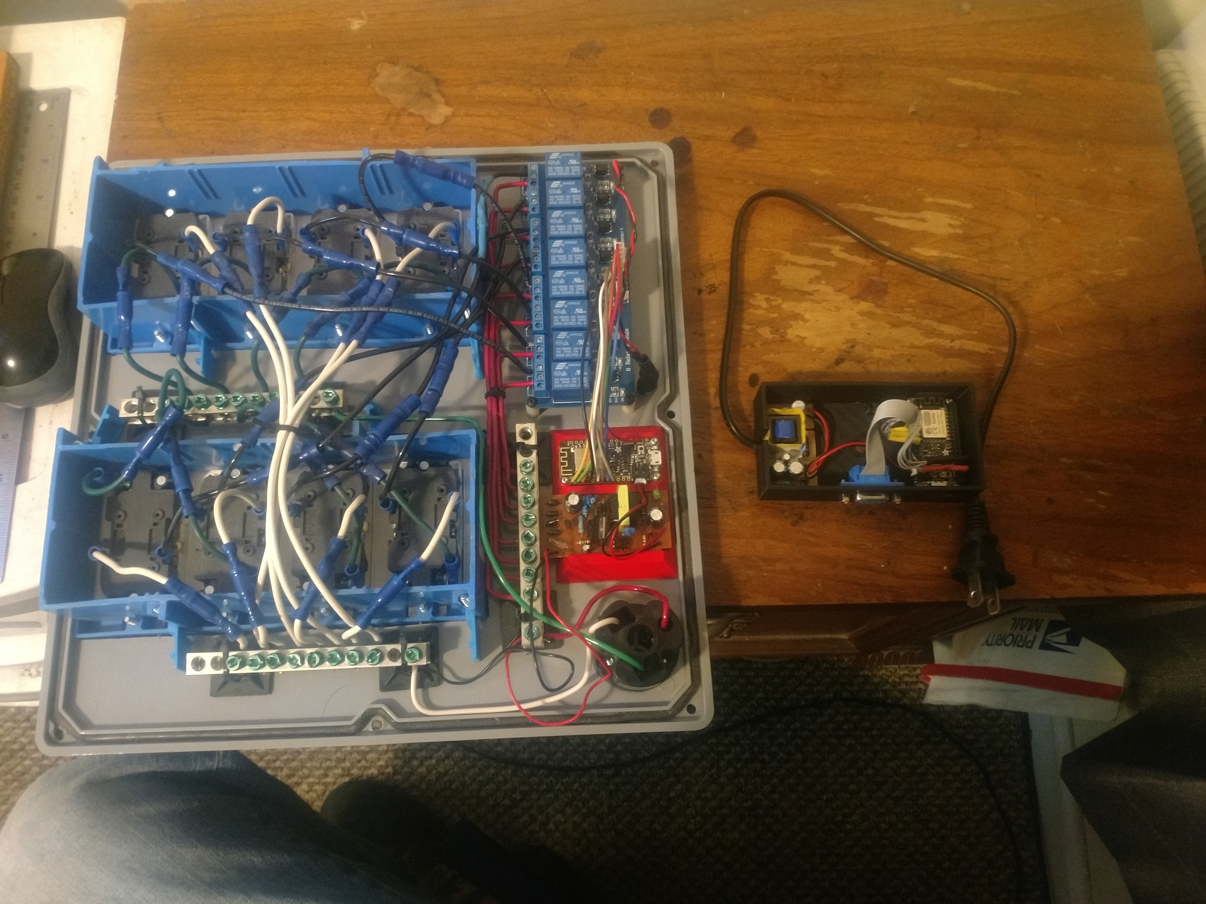
I currently have two of these 8 Channel Modules configured for true opto-isolation in that there are no shared grounds between the MCU and the relays. I pulled the jumper from JD-VCC-VCC and supply 5V4A to the JD-VCC and GND respectively. That takes care of the relay circuit. The control circuit is from the MCU’s power pin, in this case 3V on the ESP, and each of the GPIO connected sinks current supplied by the power pin to complete the logic side of the circuit. Previously, I was using an Ethermega (Arduino Mega/Ethernet combined) and this setup worked flawlessly for more than a year, but the Arduino’s limits in memory and other terms I don’t fully comprehend prevented me from expanding my project much further and I DO intend on doubling it’s size and needs in the future, so a friend talked me into considering splitting my project into several ESPs which I am now doing. It’s pretty tough going from a 5V system to a 3V3 system with only hobbiest level knowledge of circuitry and coding.
I’m glad you stated that I can get upwards of 20mA per pin as that gives me more confidence in buying 4 channel relays. I also have read that some of the pins I’m now using (2-4-5-12-13-14-15-16) may have other functions attached to them at bootup which may work against my overall desires. If my burden is halved, I think I’ll be better off finding 4 completely unused pins than 8. I’ve been wanting to slim down my project’s foot print anyways by designing and 3D printing some custom cases to hold 4 outlets, a 4chan relay and an ESP. I’ve already done this with my dosing pumps and driver circuits and it looks great. Here’s what my current hack looks like for the outlets, not pretty by any standard.
 [quote=“Skybound, post:36, topic:23360”]
I think I’ll be better off finding 4 completely unused pins
[/quote]
You should read this thread:
Having seen your setup I really would suggest that you take a look at the Sonoff 4ch or 4ch Pro devices. They’re probably cheaper than the cost of the components you’re using and are DIN rail mounting, so lend themselves to neat modular installations and kale swapping-out modules very easy. They should be easy to re-programme to work with Blynk.
Pete.
Thanks for the link. Can you also get me a link for the relays you suggested? My search I think is returning incorrect results. Also, when you have a 3D printer, mounting things is no longer a concern at all b/c I can custom design cases, standoffs and print it out in a few hours, so do I need DIN rail mounting? Is DIN rail applications for inside of a mains power panel? My application will be mounted/deployed about 100’ downstream of the mains power panel/sub panel.
This is the Sonoff 4ch Pro:
https://www.itead.cc/sonoff-4ch-pro.html
And here’s what @scargill has to say about them:
DIN rail is the thing that’s used in the back of a main ‘fusebox’ that the circuit breakers clip on to, but you can buy lengths of rail, or an empty ‘fusebox’ to give yourself an easy way of mounting hardware. Quite handy when you want to use the clip-on functionality that makes it easy to swap components out.
Pete.
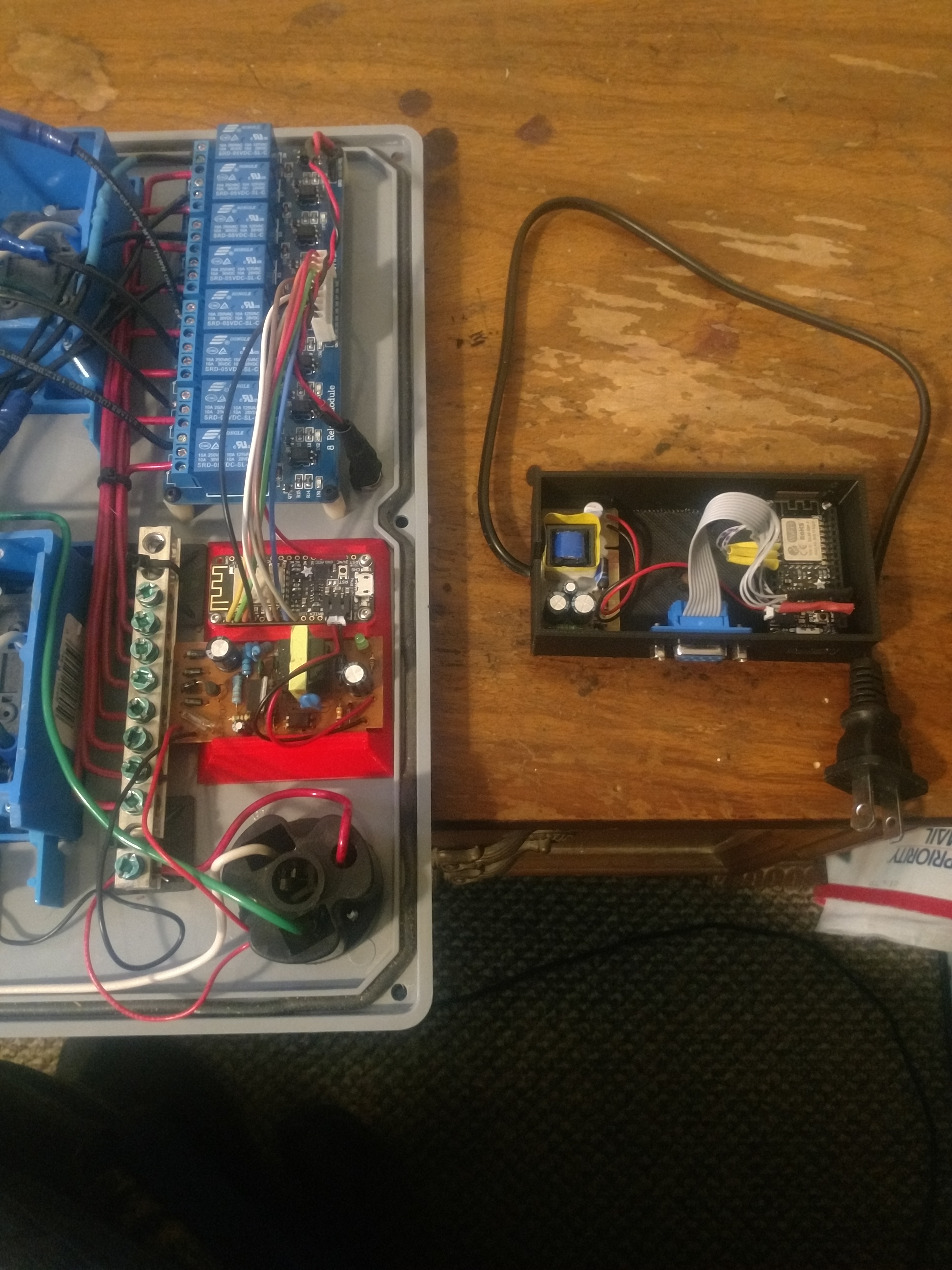
Is that a vga port?? Tell me what it is and how you’re tying that to your ESP!