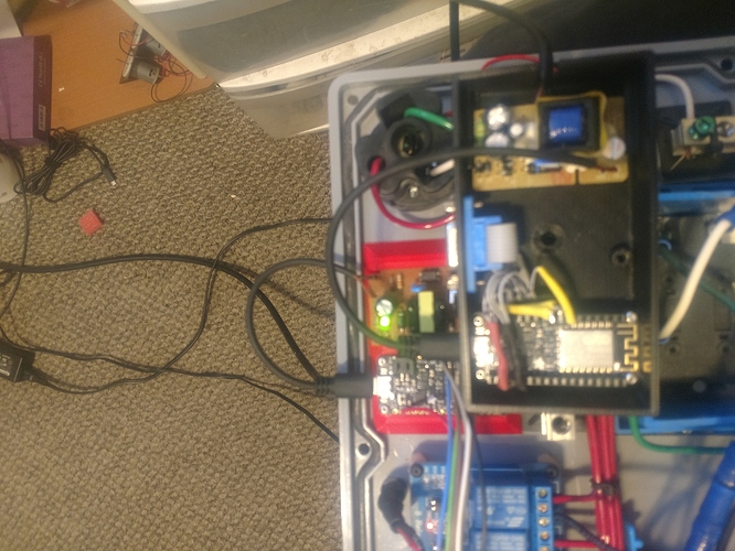
Ok, I replaced the liPoly JST connects with micro USB on both boards as pictured below.
Also, please look at the side by side of the sketches. The left is the slave with relays connected to each pin. I’ve commented out 5 of the 8 relays, so only 3 can operate. 1 of those 3 channels already performs great. So I’m now just trying to verify if my code looks good/functional for the other 2 channels. The code snippet is only for one of those channels, but the other is identical.
left side is the slave and right side is the master. Also, is pasted the handlers that are in both sketches. What I want is to press a button in my app (pumpAon on V30) “or” if the time makes the function true, send the value of 1 (TURN_ON) over the bridge on V62. The slave should see the value on V62 and execute digitalWrite commands based upon what value V62 holds.
BLYNK_WRITE(V62) {
  CC = param.asInt();  // pumpA remote
}
Does the above look correct? Below is my USB power feed from the respective hacked phone chargers.
