Hello @Kastler, you have use a TP5046, Esp32, two 18650 baterrys, BME280 and a mt 3608. What solar panels have you used?
is connected to two existing 180 W solar panels with a DC converter. the converter output is set to 5.7V which is about 0.7 volts on the input diode so about 5 volts on the tp4056. solar cells are part of an insulated system.
https://www.hestore.hu/prod_10038117.html
I´m trying to find a solution for my problem, i´m following this tutorial, https://www.hackster.io/Tiobel/esp8266-solar-weather-station-1ea3ec, used two solar panels of 1w 6v, but i gonna used the tp4056, i see that you used one diode, but you think in this case is necessary use the Mt3608?
the mt3608 is needed because the esp32 I use requires a stable 5 volt according to its datasheet, which I had to generate from the submersible rechargeable battery. The diode protects the tp4056 from reverse polarity.
I also used a test version of the circuit from a 6 volt 3.5 watt solar cell.
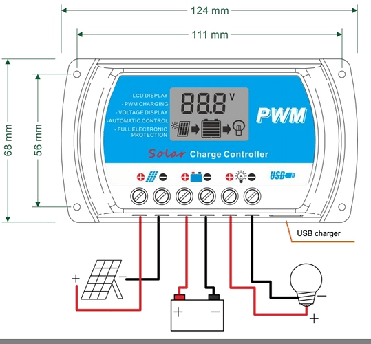
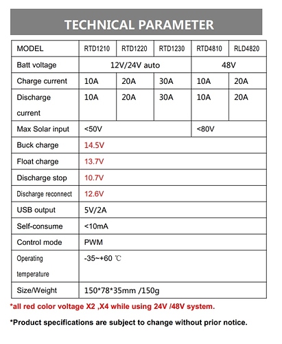
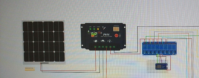
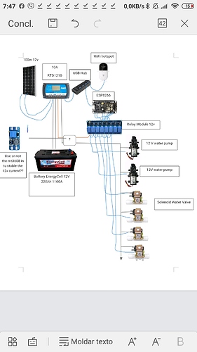
Great I gonna used this configuration in two stations with Esp8266 that you used, i have other system wit a 100w 12v Solar panel, with a pwm 10A, to supply a irrigation system, the pwm have a usb charger (output 5v/2A), to suplly the esp8266,
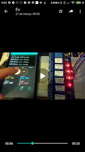
And the out(Lamp) to suplly a 8 Relay module 12V, you think is necessary use a Mt3608?
Sorry is a lot of questions but i`m learning.
You no longer need a dc converter for usb output, I think it is already directly suitable for esp. Up to a ceramic capacitor and a small electrolyte capacitor could be placed on it for power supply filtration.
Sorry my english, im use Google translator.
see the current consumption of the relay module input and the maximum load of the esp output. if the load on the esp output is higher then you can connect it directly. Whether the relay module can be controlled with esp 3.3 volts.
There aren’t really enough suitable pins on an ESP8266 to drive an 8-way relay and although your diagram shows only 6 of the relays in use, the downwards arrow implies that you may be adding more devices in future.
If you want to drive an 8-way relay you’d be better with an ESP32, or an I2C expander like these:
Also, I’d get a 5v relay board rather than a 12v one.
I think I’d also avoid the USB hub as a way of splitting the 5v power supply.
Is the WiFi hotspot going to be connected via an Ethernet cable? If not then I cant really see it’s value.
Pete.
Hello @PeteKnight only use 6 pins and is working
The wifi hotspot have a sim card is necessary because this gonna stay on a remoted area.
And if the water pumps and solenoid valve work on 12 v, its possible use a 5v relays?
So it’s really a cellular router?
I think you’re getting confused between the actuating voltage of the relays and the maximum load switching voltage/current.
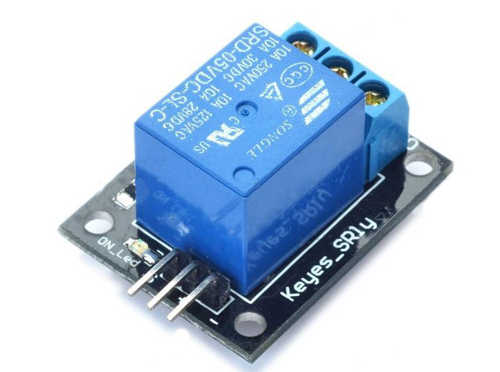
The relay modules I use have relays which are capable of switching 10A at 240v and 10A at 30v. This is about the voltage and current rating of the load contacts, nothing else.
The coil voltage of these relays is 5v and the Vcc pin of the relay board requires 5v + DC.
Using this type of relay you’re less likely to ever expose your ESP’s GPIO pins to more than 5v (which they can tolerate without any issues), regardless of what you do with the JD-VCC pins on the relay board.
Pete.
I’m not going to comment on your latest image because it’s so far removed from what we’ve been discussing.
If you already have a 12v relay module and you’re happy with it then stick with it. I’m just saying that I always choose 5v relay modules because of the issues I outlined earlier.
Pete.
Ok @PeteKnight i use the 12 v module, and is necessary use the mt3608?
And you think is better change the power supply to the Wi-Fi hotspot and the esp8266.
Why, what purpose does it serve?
What I said is that I wouldn’t use a USB hub as a 5v power splitter for these devices - it’s not an efficient way to do it and it’s one more potential point of failure.
Simply split the 5v output yourself to power the Cellular Router and ESP8266.
Pete.
Ok Usb splitter checked is a better solution.
The mt3608 was because i have afraid that the current that came from the pwm controller, fried the relay, if have some increase of energy(seriously i don’t have any formation in electronics).
