You can search PZEM004Tv30 Library.
Wow, that’s not the answer that I am looking for. I need accumulated piece of code so I can add it to my original code (first post) so other PZEM users can have a complete code.
If I just acting like your response then I would not create this original thread and list all my code here for you to used.
So, please share your code
I just switched to use PZEM004Tv30 Lib instead of your code.
Previous, I had tried wrote a Accumulate Function but It has didn’t work exactly yet. I still try to improve it but maybe there are problems when store Accumulate variable to EEPROM, i still don’t know ?!?! 
My Idea is:
 1. Add 1 variable for Accumulate Active Energy (AAE), this variable will store in EEPROM. Every time function pzemupdate() work, it readout AAE and accumulate new value to AAE then store AAE back to EEPROM.
2. Add 1 data[] array to compare the Value read from PZEM004T module if the reset happen AAE > AE (AE = your PPR) then AAE = (( AE - d[i] ) + AAE), for normal AAE = AE.
///add EEPROM.h
#include <EEPROM.h>

double U_PR, I_PR, P_PR, PR_F, PR_PF, PR_alarm, AE;
double AAE = 0; //Variables for Accumutale Active Energy
double data[]={0,0,0};  //Variables for Electric Measuring
int i=0;                //index for data[];
int addr = 0; //Address in EEPROM where to store value of AAE - ACCUMULATE_ACTIVE_ENERGY


//PZEM DATA UPLOAD TO BLYNK SERVER

void pzemupdate()
{
  result = node.readInputRegisters(0x0000, 10);
  if (result == node.ku8MBSuccess)
  {
    U_PR      = (node.getResponseBuffer(0x00)/10.0f);
    I_PR      = (node.getResponseBuffer(0x01)/1000.000f);
    P_PR      = (node.getResponseBuffer(0x03)/10.0f);
    PR_F      = (node.getResponseBuffer(0x07)/10.0f);
    PR_PF     = (node.getResponseBuffer(0x08)/100.0f);
    PR_alarm  = (node.getResponseBuffer(0x09));
    AE        = (node.getResponseBuffer(0x05)/1000.0f);
  }
  //Read AAE from EEPROM
    EEPROM.begin(512);         //Initialize EEPROM
    EEPROM.get(addr,AAE);    //Read AAE from EEPROM
    addr += sizeof(double);    //Move address to the next byte after AAE
    EEPROM.get(addr,data); //Read data[] from EEPROM
    addr += sizeof(data);    //Move address to the next byte after data[]
    EEPROM.get(addr,addr);   //Read addr from EEPROM
    addr = 0;
    Serial.println("Read previous AAE value !");

    if(AAE > AE)
    {
      AAE = (AAE + (AE - data[i]));
    }
      else
      {
        AAE = AE;
      }
    i++;
    if(i == 3)
    {
      i = 0;
    }
    data[i] = AE;

    EEPROM.put(addr,AAE);      //Write AAE in EEPROM Flash Address
    addr += sizeof(double);    //Move address to the next byte after AAE
    EEPROM.put(addr,data);   //Write data[] in EEPROM Flash Address
    addr += sizeof(data);    //Move address to the next byte after data[]
    EEPROM.put(addr,addr);     //Write data[] in EEPROM Flash Address
    addr += sizeof(addr);      //Move address to the next byte after data[]
    EEPROM.end();              //Execute Write EEPROM & release the RAM copy of EEPROM contents
    Serial.println("Store AAE to EEPROM !");

  Serial.print("U_PR:     "); Serial.println(U_PR);   // V
  Serial.print("I_PR:     "); Serial.println(I_PR,3);   //  A
  Serial.print("P_PR:     "); Serial.println(P_PR);   //  W
  Serial.print("AE:      "); Serial.println(AE,3);   // kWh
  Serial.print("AAE:      "); Serial.println(AAE,3);   // kWh
  Serial.print("PR_F:     "); Serial.println(PR_F);    // Hz
  Serial.print("PR_PF:    "); Serial.println(PR_PF);
  Serial.print("PR_alarm: "); Serial.println(PR_alarm,0);
  Serial.println("====================================================");

  Blynk.virtualWrite(vPIN_VOLTAGE,                  U_PR);
  Blynk.virtualWrite(vPIN_CURRENT_USAGE,            I_PR);
  Blynk.virtualWrite(vPIN_ACTIVE_POWER,             P_PR);
  Blynk.virtualWrite(vPIN_ACTIVE_ENERGY,            AE);
  Blynk.virtualWrite(vPIN_ACCUMULATE_ACTIVE_ENERGY, AAE);
  Blynk.virtualWrite(vPIN_FREQUENCY,                PR_F);
  Blynk.virtualWrite(vPIN_POWER_FACTOR,             PR_PF);
  Blynk.virtualWrite(vPIN_OVER_POWER_ALARM,         PR_alarm);

  delay(1000);
}
@4eyes please edit your post, using the pencil icon at the bottom, and add triple backticks at the beginning and end of your code so that it displays correctly.
Triple backticks look like this:
```
Pete.
Ok, Thanks ! 
At what time interval is your pzemupdate() function being called?
Pete.
every 1s
//Timer for Tasks
  timerTask1 = timer.setInterval(1000, pzemupdate);
That means your EEPROM memory will die after around 27 hours, as each memory location is good for around 100,000 read/write operations.
You should be using SPIFFS or LittleFS (preferably the latter, as SPIFFS is now deprecated) to store your NVR data.
Pete.
1 Like
Oh, I forgot that. Thanks !
Ok, I will try your suggest. But is my Accumulate Code correct ? 
if(AAE > AE)
    {
      AAE = (AAE + (AE - data[i]));
    }
      else
      {
        AAE = AE;
      }
    i++;
    if(i == 3)
    {
      i = 0;
    }
    data[i] = AE;
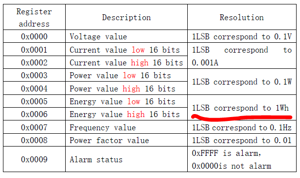
According to the manual (table attached below), energy is transmitted in 4 bytes, 1LSB=1Wh, so the maximum possible value is 65532 Wh =65.534 kWh, approximately 65.5kWh, so this would be the reason why the module resets to zero.
I understand from 4eyes’ post that the PZEM004Tv30 library overcomes this problem. Are you sure 4eyes? Because there is no way that that library can read more than 4 bytes from PZEM, unless the library employs some software trick (as the in code you posted).
I have used the library with Arduino nano, but it’s difficult for me to test that as I haven installed the PZEM in a real installation (just a test setup), so it’s very difficult I can get it to acumulate so much energy
This is PZEM004Tv30 Lib Source Code:
Active Energy is Accumulate like this:
 _currentValues.energy =  ((uint32_t)response[13] << 8 | // Raw Energy in 1Wh
                              (uint32_t)response[14] |
                              (uint32_t)response[15] << 24 |
                              (uint32_t)response[16] << 16) / 1000.0;
/*!
 * PZEM004Tv30::energy
 *
 * Get Active energy in kWh since last reset
 *
 * @return active energy in kWh
*/
float PZEM004Tv30::energy()
{
    if(!updateValues()) // Update vales if necessary
        return NAN; // Update did not work, return NAN

    return _currentValues.energy;
}

/*!
 * PZEM004Tv30::updateValues
 *
 * Read all registers of device and update the local values
 *
 * @return success
*/
bool PZEM004Tv30::updateValues()
{
    //static uint8_t buffer[] = {0x00, CMD_RIR, 0x00, 0x00, 0x00, 0x0A, 0x00, 0x00};
    static uint8_t response[25];

    // If we read before the update time limit, do not update
    if(_lastRead + UPDATE_TIME > millis()){
        return true;
    }

    // Read 10 registers starting at 0x00 (no check)
    sendCmd8(CMD_RIR, 0x00, 0x0A, false);


    if(recieve(response, 25) != 25){ // Something went wrong
        return false;
    }


    // Update the current values
    _currentValues.voltage = ((uint32_t)response[3] << 8 | // Raw voltage in 0.1V
                              (uint32_t)response[4])/10.0;

    _currentValues.current = ((uint32_t)response[5] << 8 | // Raw current in 0.001A
                              (uint32_t)response[6] |
                              (uint32_t)response[7] << 24 |
                              (uint32_t)response[8] << 16) / 1000.0;

    _currentValues.power =   ((uint32_t)response[9] << 8 | // Raw power in 0.1W
                              (uint32_t)response[10] |
                              (uint32_t)response[11] << 24 |
                              (uint32_t)response[12] << 16) / 10.0;

    _currentValues.energy =  ((uint32_t)response[13] << 8 | // Raw Energy in 1Wh
                              (uint32_t)response[14] |
                              (uint32_t)response[15] << 24 |
                              (uint32_t)response[16] << 16) / 1000.0;

    _currentValues.frequeny =((uint32_t)response[17] << 8 | // Raw Frequency in 0.1Hz
                              (uint32_t)response[18]) / 10.0;

    _currentValues.pf =      ((uint32_t)response[19] << 8 | // Raw pf in 0.01
                              (uint32_t)response[20])/100.0;

    _currentValues.alarms =  ((uint32_t)response[21] << 8 | // Raw alarm value
                              (uint32_t)response[22]);

    // Record current time as _lastRead
    _lastRead = millis();

    return true;
}
To avoid EEPROM wearing, a good approach would be to save in EEPROM just the number of times the limit has been reached (or increase a counter each time PZEM energy reading falls below previous reading).
The total accumulated energy in Wh would be = PZEM energy (Wh) + (EEPROM counter * 65532).
EEPROM is virtually obsolete and the thing that replaced it (SPIFFS) is heading the same way.
I’ve used EEPROM before and it’s a pain.
SPIFFS is a doddle in comparison, and apparently LittleFS is also simple.
Of course, you don’t really need to use any of these if you use Blynk (assuming that your internet connection stays up most of the time) as you can write the values to a virtual pin and retrieve them at boot-up with a Blynk.syncVirtual command.
Pete.
Thanks ! Now I understand.
Key’s Code only read 16 bits Low value of Current, Power and Energy Register. So
Maximum Current can display is 65.5 A
Maximum Active Power can display is 6553.5 W
Maximum Active Energy can display is 65.5 kWh
The problem not usually happen with Current and Active Power because they are not Accumulated Parameters. 
The problem only solved by read 2 registers Value High and Value Low then combine them
So we don’t need Accumulate Function anymore 
I’m afraid I was completely wrong!!
Current, power, and energy use 32 bits, so 2^32 is the maximum value for them (65532^2).
65532 would be the limit for 2 bytes. I mistook nibbles for bytes…
So, if energy resets to zero above 65,532kW, this would indicate the soft is only getting 2 of the 4 bytes, as 4eyes said
(I noticed the error when I read 4eyes said the maximum value for current would be 65 amp, when the module is specified for 100A)
BTW, PZEMs firmware does not take full advantage of the main IC’s capabilities (V9981). For example, according to the datasheet:
https://www.javanelec.com/CustomAjax/GetAppDocument/84d8dfa1-17fe-4430-8ccc-e6a7901446f8
There are registers for positive and negative energy accumulators (page 269) but the module does not provide information about imported/exported energy
I’m not very sure but could then the problem be solved just substituting the original PPR calculation:
PPR = (node.getResponseBuffer(0x05)/1000.0f);
For this one?:
PPR = ((node1.getResponseBuffer(0x05) + (node1.getResponseBuffer(0x06)*65532))/1000.0f);
Something like that would also have to be done with current and power (at least, if you’re expecting more than 65,5 amp and/or more than 65,5 kW)
I confirm this solution is work ! 
Hi Pete
Thank you for your help previously with the code, however the issue now is that serial monitor displays all readings as 0.00. I also tried loading Khoih’s code & it returns a “cant get data”
I am using the PZEM-004 V3 (with digital display) & a Wemos mini. Connections are per your instruction…
- ESP8266 5V ==> PZEM 5V
- ESP8266 G ==> PZEM GND
- ESP8266 Rx ==> PZEM D6
- ESP8266 Tx ==> PZEM D5
I have also tried adding the 1k ohm resistor to the PZEM. With the resistor added I have tried connecting both the 3.3v & the 5v on the mini to the PZEM vcc. Both options to no avail.
Its worth noting that with PZEM connected to an AC load, its onboard digital display reads the correct Voltage, Current, Power & total Power. Could it be that i have a faulty TTL output?
Any help would be appreciated.
Phil
I think that maybe @key’s wiring description is a little confusing.
The comments in the code are more accurate:
What this means is that pin D5 on the NodeMCU is the Software Serial Rx pin. This has to connect to the Tx pin on the PZEM.
D6 on the NodeMCU is SoftwareSerial Tx and connects to Rx on the PZEM.
So, I think that the description should actually read like this:
ESP8266 5V ==>      PZEM 5V
ESP8266 G ==>       PZEM GND
ESP8266 D5 (Rx) ==> PZEM Tx
ESP8266 D6 (Tx) ==> PZEM Rx
Pete.
Hi Pete
Thanks for the clarification however i do have it connected as you have noted.
Phil