The inconvenience arises when I connect the fan in one of the channels, when I increase to the maximum the slider in blynk, the fan turns on without problems, but after a while I try to leave the slider to zero but it does not respond, the fan does not turn off, and I have to disconnect everything and restart, I tried with three fans , and one of the three works perfectly, turns me on and off, then my question is, will the other two fans consume more current than the dimmer can withstand, or what could it be?
On this page you can find the characteristics that the dimmer has, and there is a part that says
Connected LOAD power for each channel 500W long-term and 1000W short-term.
I do not understand very well the long-term and short-term, but I imagine that it refers to the current that each channel can support.
I am still looking for a Blynk related question here
Means will run all day at up to 500W and short spikes, a few seconds or so, at 1000W… That of course is Chinesium ratings… I would probably reduce those figures by 50% at least
Besides… if you have a fan that pulls 500W… then stop using it and give it back to the fire department for their use in clearing buildings full of smoke
Whatever floats yer boat
Probably some of the fans have their own circuitry that is interfering with these variable dimmer boards (which are generally meant for lighting, not motors).
The ac dimmer is designed so that it can work with fans, they themselves specify it on the ebay page, but you are right, this is a Blynk community and my problem is outside of it, I apologize.
Never trust in ebay web page descriptions I was looking as the silk screening on the board itself… which clearly claims lighting
That said, if the sliders and MCU can send a PWM signal that the device can work with, then any issues you are running into will be primarily due the the device you are controlling… basic incandescent lights rarely have circuitry that interferes but some LED and most all CFL types do… and the same will go for some fans that already have speed control built in.
And while it says snubbers… well, some larger motors might still kill the triacs… trial and error is your only option to determine compatibility.
Were you able to dim the fan or just turn it on?
As per your comments, I guess you are not taking into consideration the sync pin, are you? In that case, review the way a dimmer with zero cross works.
I know how the dimmer works, dim the lights, and when I say that the fan worked for me it is because when I raise the slider or decrease it it is able to control the fan speed, that is, I can give the fan any speed, the problem I have with the other fans is to maximize the level of speed, when I want to turn it off does not work, it stays at the maximum.
I also know that you need a pin that is the Sync, so you can dim the voltage, or else, it would not work for me.
#define BLYNK_PRINT Serial
#include <SPI.h>
#include <Ethernet.h>
#include <BlynkSimpleEthernet.h>
#include  <TimerOne.h>          // Avaiable from http://www.arduino.cc/playground/Code/Timer1
volatile int i=0;               // Variable to use as a counter volatile as it is in an interrupt
volatile boolean zero_cross=0;  // Boolean to store a "switch" to tell us if we have crossed zero
int AC_pin = 3;                // Output to Opto Triac
int brightness = 120;           // Dimming level (0-128)  0 = on, 128 = 0ff
int freqStep = 65;    // This is the delay-per-brightness step in microseconds.
const int analogPin = A0;
int value;
// You should get Auth Token in the Blynk App.
// Go to the Project Settings (nut icon).
char auth[] = "xxxxxxxxxxxxxxxxxxxxxxx";

#define W5100_CS  10
#define SDCARD_CS 4


void setup()
{
  pinMode(SDCARD_CS, OUTPUT);
  digitalWrite(SDCARD_CS, HIGH); // Deselect the SD card
  pinMode(AC_pin, OUTPUT);                          // Set the Triac pin as output
  attachInterrupt(0, zero_cross_detect, RISING);    // Attach an Interupt to Pin 2 (interupt 0)
  Timer1.initialize(freqStep);                      // Initialize TimerOne library
  Timer1.attachInterrupt(dim_check, freqStep);
  Serial.begin(9600);
  Blynk.begin(auth);
}

  BLYNK_WRITE(V1)//      slider brillo
{
 int brillo = param.asInt();
brightness=brillo;
}

void zero_cross_detect() {
  zero_cross = true;
  i=0;
  digitalWrite(AC_pin, LOW);       // turn off TRIAC (and AC)
}
// Turn on the TRIAC at the appropriate time
void dim_check() {

  if(zero_cross == true) {

    if(i>=brightness) {
      digitalWrite(AC_pin, HIGH); // turn on light
      i=0;  // reset time step counter
      zero_cross = false; //reset zero cross detection
    }
    else {
      i++; // increment time step counter
    }
  }
}
void loop()
{
  Blynk.run();
}
Another thing, the dimmer is able to control the speed of the fan, when I leave it more or less in half it works well, the problem is when the fan motor starts to maximum, I try to decrease it but still at the maximum.
Can you supply info (make/model/picture) on the fan that does work and one of the ones that doesn’t… not that we can fix a fan but it might help in confirming the issue.
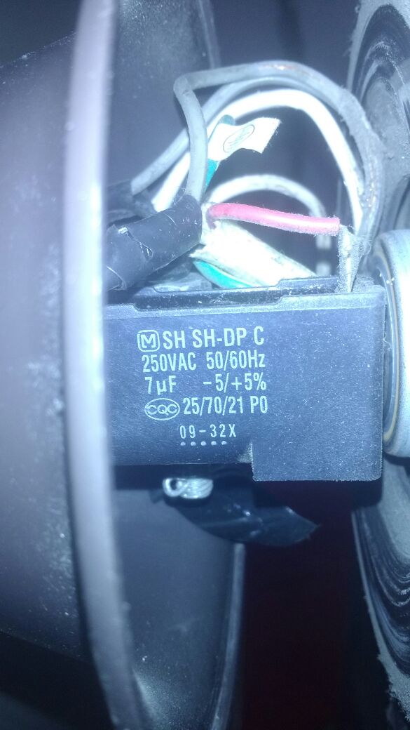
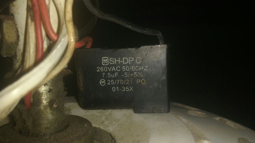
Of course, in this site is all the specifications of the fan that works for me, and in this one is one that does not work for me, both are from the same brand, but from a different model, maybe it’s a cause, I do not know.
Something I tried was to change the capacitor to the fan that does not work, but it’s still the same
Ahh, multi speed ceiling fans… or capacitor start, split phase induction motor. The capacitor is there to assist in starting and power correction while running… but I believe there should be some form of Triac based regulator for speed control… and that is what you need to bypass/replace with your controller board… assuming it can handle it (again, I suspect it is more geared toward lighting).
As suspected, none of your issues are on the software side… Google around for Arduino/MCU controlled ceiling fans, and try to determine the wiring/control options from the many sites that refer directly to that.
Only after getting that working perfectly need you worry about Blynk control of the Arduino/MCU.
There’s a wiring diagram on page 11 of this installation manual: https://www.manualslib.com/manual/1093706/Kdk-M56xg.html?page=11#manual
It shows just two capacitors, one built into the fan and one in the wall controller. I assume you’ve completely removed the wall controller from your wiring?
My guess is that if you’re testing the speed controller with the fans in situ on the ceiling then something is changing during testing - either you’re not connecting the fans up correctly, or maybe you have a dodgy connection on a breadboard. Try getting both fans side by side on the workbench and testing them that way.
What happens is that the fans are already installed, I would have to lower them and test them, with respect to the switch that is on the wall I removed it, and I am connected from the dimmer directly to the fan