Which library has the two .h files in it Pete ? ie update.h and HTTPclient.h
Cheers
kev
Which library has the two .h files in it Pete ? ie update.h and HTTPclient.h
Cheers
kev
Update and HTTPClient libraries bundled with the esp32 Arduino core
You need to use…
#include <ESP8266HTTPClient.h>
instead of…
#include <HTTPClient.h>
I think that the ESP8266 version of update.h is called ESP8266httpUpdate.h
Pete.
will try pete thanks
Still not working Pete. I am getting confused here, is this minimal code is to program over the AIR via wifi and also to run code via wifi correct ?? if so where are the SSID and passwords etc ?
Cheers
kev
It’s code to add to your existing static provisioning sketch to give OTA via Blynk.Air
Maybe you should start a new topic with your Legacy code and the changes that you’ve made so far to make it Blynk IoT compatible.
Pete.
the Update object is directly in core for esp8266 arduino
hmm it always surprises me that there is no simple sketch for each device type to set it up for OTA etc. I read through the docs for Blynk AIR and its not straightforward at all. Life was a lot easier with Blynk 1.0
Cheers
kev
so “Air” is not really a Blynk 1 v. Blynk 2.
the Edgent examples incorporate “Air”. did you try the Edgent example?
Which docs, and which part don’t you find straightforward?
Blynk.Air is slightly less convenient than Arduino OTA in that you don’t choose a network port in the IDE, but more convenient because you have far more control over the way that shipments are managed, and the way that the device doesn’t need to be on the same network.
TBH, there are only a handful of differences between Blynk Legacy and Blynk IoT. If you want to use Arduino OTA with Blynk IoT then that’s fine.
I really don’t want this discussion to be cluttering-up this Blynk.Air minimal code topic, so I will be splitting the past posts off in to a new topic or deleting them entirely. Either do what I suggested earlier…
and I’ll merge these last posts in to that topic, or expect the last few posts in this topic to disappear by tomorrow.
Pete.
Yes got edgent to work fine, but dont like having to have all the .h files etc in the sketch folder - just not tidy, and as I said to Pete earlier I don’t really need to do provisioning, I just want the simplest way to program my ESP8266 OTA and so far (other than edgent) I’m getting nowhere!
Pete,
But the point is I am trying just to get the minimalist code work standalone, which surely is relevant to this post. I simply cant get it to work. The latest attempt now compiles and uploads but just doesnt connect.
It attempts to connect 0.0.0.0 repeatedly. This is just using the minimalist code in this thread but for ESP8266. So is this ok here ?
here is the code anyway and if you want me to start a new thread I will.
Cheers
kev
#define BLYNK_TEMPLATE_ID "redacted"
#define BLYNK_TEMPLATE_NAME "redacted"
#define BLYNK_AUTH_TOKEN "redacted"

#define BLYNK_FIRMWARE_VERSION "1.1.1"

#define BLYNK_PRINT Serial

#include <ESP8266WiFi.h>
#include <BlynkSimpleEsp8266.h>

//ESP32
//#include <Update.h>
//#include <HTTPClient.h>

//ESP8266
#include <ESP8266HTTPClient.h>
#include <ESP8266httpUpdate.h>
//________________________________________________________________
String overTheAirURL = "";

#define WIFI_SSID "redacted"         //Enter Wifi Name
#define WIFI_PASS "redacted"          //Enter wifi Password


void setup() {
  Serial.begin(115200);

}


void loop(){
  Blynk.run();
    delay(500);
}

BLYNK_WRITE(InternalPinOTA) {
 Serial.println("OTA Started");
  overTheAirURL = param.asString();
 Serial.print("overTheAirURL = ");
 Serial.println(overTheAirURL);
  WiFiClient my_wifi_client;
  HTTPClient http;
  http.begin(my_wifi_client, overTheAirURL);
  int httpCode = http.GET();
 Serial.print("httpCode = ");
 Serial.println(httpCode);
  if (httpCode != HTTP_CODE_OK) {return;}
  int contentLength = http.getSize();
 Serial.print("contentLength = ");
 Serial.println(contentLength);
  if (contentLength <= 0) {return; }
  bool canBegin = Update.begin(contentLength);
 Serial.print("canBegin = ");
 Serial.println(canBegin);
  if (!canBegin) { return;}
  Client& client = http.getStream();
  int written = Update.writeStream(client);
 Serial.print("written = ");
 Serial.println(written);
  if (written != contentLength) {return;}
  if (!Update.end()) {return;}
  if (!Update.isFinished()) {return;}
reboot();
}

void reboot()
{
 Serial.println("Rebooting after OTA Update...");
#if defined(ARDUINO_ARCH_MEGAAVR)
  wdt_enable(WDT_PERIOD_8CLK_gc);
#elif defined(__AVR__)
  wdt_enable(WDTO_15MS);
#elif defined(__arm__)
  NVIC_SystemReset();
#elif defined(ESP8266) || defined(ESP32)
  ESP.restart();
#else
  #error "MCU reset procedure not implemented"
#endif
  for (;;) {}
}
//_________
Your code doesn’t have a Blynk.begin() command, or alternatively any code that creates a WiFi connection and then tells the sketch which credentials (Auth token) to use when it encounters a Blynk.connect() or Blynk.run() command.
You’re approaching this from totally the wrong direction.
It’s generally very simple and straightforward to convert a legacy sketch 8into an IoT sketch. It can be as simple as just adding the three lines of Blynk.configuration firmware from the device info page in the web console, and using BLYNK_AUTH_TOKEN rather than auth your Blynk connection command.
Post your existing Legacy sketch here, with those changes made, and details of what you see in your serial monitor when you run the sketch.
Pete.
OK Pete here we go and thanks for all your help once again and I agree I am totally approaching this from the wrong angle!
// 4 Way Speaker Switch WiFi controller via Blynk  and push button
// Written by kevin Downes 17/04/2019
//
// 17/04/219 v1.0.0 - Release

//  These are the only 2 new lines I have added
#define BLYNK_TEMPLATE_ID "redacted"
#define BLYNK_TEMPLATE_NAME "redacted"


#define BLYNK_PRINT Serial
#include <ESP8266WiFi.h>
#include <ESP8266mDNS.h>
#include <WiFiUdp.h>
#include <ArduinoOTA.h>
#include <BlynkSimpleEsp8266.h>

char auth[] = "redacted";
char ssid[] = "redacted";
char pass[] = "redacted";

BlynkTimer timer;

int allSwitch;
bool pressed1 = false;
bool pressed2 = false;
bool pressed3 = false;
bool pressed4 = false;
bool resetFlag = true;  // TRUE when the hardware has been reset.

int RELAY12_pin = 5;      // Relay 1&2 pin D1
int RELAY34_pin = 4;      // Relay 3&4 pin D2
int RELAY56_pin = 0;      // Relay 5&6 pin D3
int RELAY78_pin = 2;      // Relay 7&8 pin D4
int Switch1_pin = 14;     // Digital pin for switch 1 input D5
int Switch2_pin = 12;     // Digital pin for switch 2 input D6
int Switch3_pin = 13;     // Digital pin for switch 3 input D7
int Switch4_pin = 15;     // Digital pin for switch 4 input D8

void setup() {

  // put your setup code here, to run once:
  Serial.begin(115200);
  Serial.println("Booting");
  WiFi.mode(WIFI_STA);
  WiFi.begin(ssid, pass);
  while (WiFi.waitForConnectResult() != WL_CONNECTED) {
    Serial.println("Connection Failed! Rebooting...");
    delay(5000);
    ESP.restart();
  }

  ArduinoOTA.onStart([]() {
    String type;
    if (ArduinoOTA.getCommand() == U_FLASH)
      type = "sketch";
    else // U_SPIFFS
      type = "filesystem";

    // NOTE: if updating SPIFFS this would be the place to unmount SPIFFS using SPIFFS.end()
    Serial.println("Start updating " + type);
  });
  ArduinoOTA.onEnd([]() {
    Serial.println("\nEnd");
  });
  ArduinoOTA.onProgress([](unsigned int progress, unsigned int total) {
    Serial.printf("Progress: %u%%\r", (progress / (total / 100)));
  });
  ArduinoOTA.onError([](ota_error_t error) {
    Serial.printf("Error[%u]: ", error);
    if (error == OTA_AUTH_ERROR) Serial.println("Auth Failed");
    else if (error == OTA_BEGIN_ERROR) Serial.println("Begin Failed");
    else if (error == OTA_CONNECT_ERROR) Serial.println("Connect Failed");
    else if (error == OTA_RECEIVE_ERROR) Serial.println("Receive Failed");
    else if (error == OTA_END_ERROR) Serial.println("End Failed");
  });
  ArduinoOTA.begin();
  Serial.println("Ready");
  Serial.print("IP address: ");
  Serial.println(WiFi.localIP());

  // set outputs for relay channels  - each pin fires a pair of relays
  pinMode(RELAY12_pin, OUTPUT); //D1
  digitalWrite(RELAY12_pin, HIGH);
  pinMode(RELAY34_pin, OUTPUT); //D2
  digitalWrite(RELAY34_pin, HIGH);
  pinMode(RELAY56_pin, OUTPUT); //D3
  digitalWrite(RELAY56_pin, HIGH);
  pinMode(RELAY78_pin, OUTPUT); //D4
  digitalWrite(RELAY78_pin, HIGH);

  //set input for each switch
  pinMode(Switch1_pin, INPUT); //D5
  pinMode(Switch2_pin, INPUT); //D6
  pinMode(Switch3_pin, INPUT); //D7
  pinMode(Switch4_pin, INPUT); //D8

  Blynk.syncVirtual(V80);
  Blynk.syncVirtual(V81);
  Blynk.syncVirtual(V82);
  Blynk.syncVirtual(V83);
  Blynk.syncVirtual(V126);

  if (resetFlag == true) { // we need this to stop a switch detect after a reset/power failure
    pressed1 = true;
    pressed2 = true;
    pressed3 = true;
    pressed4 = true;
    resetFlag = false;
  }

  timer.setInterval(100, Switch1_detect);
  timer.setInterval(100, Switch2_detect);
  timer.setInterval(100, Switch3_detect);
  timer.setInterval(100, Switch4_detect);
  timer.setInterval(200, sigStrength);
}

void sigStrength()
{
  long rssi = WiFi.RSSI();
  Blynk.virtualWrite(V90, rssi);
}


void Switch1_detect()
{
  if (digitalRead(Switch1_pin) == 1 && pressed1 == false) {
    digitalWrite(RELAY12_pin, !digitalRead(RELAY12_pin));
    Blynk.virtualWrite(V40, !digitalRead(RELAY12_pin));
    Blynk.virtualWrite(V80, digitalRead(RELAY12_pin));
    pressed1 = true;
  }
  else if (digitalRead(Switch1_pin) == 0 && pressed1 == true) {
    pressed1 = false;
  }
}

void Switch2_detect()
{
  if (digitalRead(Switch2_pin) == 1 && pressed2 == false) {
    digitalWrite(RELAY34_pin, !digitalRead(RELAY34_pin));
    Blynk.virtualWrite(V41, !digitalRead(RELAY34_pin));
    Blynk.virtualWrite(V81, digitalRead(RELAY34_pin));
    pressed2 = true;
  }
  else if (digitalRead(Switch2_pin) == 0 && pressed2 == true) {
    pressed2 = false;
  }
}

void Switch3_detect()
{
  if (digitalRead(Switch3_pin) == 1 && pressed3 == false) {
    digitalWrite(RELAY56_pin, !digitalRead(RELAY56_pin));
    Blynk.virtualWrite(V42, !digitalRead(RELAY56_pin));
    Blynk.virtualWrite(V82, digitalRead(RELAY56_pin));
    pressed3 = true;
  }
  else if (digitalRead(Switch3_pin) == 0 && pressed3 == true) {
    pressed3 = false;
  }
}

void Switch4_detect()
{
  if (digitalRead(Switch4_pin) == 1 && pressed4 == false) {
    digitalWrite(RELAY78_pin, !digitalRead(RELAY78_pin));
    Blynk.virtualWrite(V43, !digitalRead(RELAY78_pin));
    Blynk.virtualWrite(V83, digitalRead(RELAY78_pin));
    pressed4 = true;
  }
  else if (digitalRead(Switch4_pin) == 0 && pressed4 == true) {
    pressed4 = false;
  }
}

BLYNK_WRITE(V40)  // Runs every-time switch widget V40 is toggled.
{
  digitalWrite(RELAY12_pin, !digitalRead(RELAY12_pin));        // Toggle relay 1&2
  Blynk.virtualWrite(V80, digitalRead(RELAY12_pin)); // Store relay 1&2 state in V80
}

BLYNK_WRITE(V41)  // Runs every-time switch widget V41 is toggled.
{
  digitalWrite(RELAY34_pin, !digitalRead(RELAY34_pin));        // Toggle relay 3&4
  Blynk.virtualWrite(V81, digitalRead(RELAY34_pin)); // Store relay 3&4 state in V81
}

BLYNK_WRITE(V42)  // Runs every-time switch widget V42 is toggled.
{
  digitalWrite(RELAY56_pin, !digitalRead(RELAY56_pin));        // Toggle relay 5&6
  Blynk.virtualWrite(V82, digitalRead(RELAY56_pin)); // Store relay 5&6 state in V80
}

BLYNK_WRITE(V43)  // Runs every-time switch widget V43 is toggled.
{
  digitalWrite(RELAY78_pin, !digitalRead(RELAY78_pin));        // Toggle relay 7&8
  Blynk.virtualWrite(V83, digitalRead(RELAY78_pin)); // Store relay 7&8 state in V83
}

BLYNK_WRITE(V80)
{
  int V80_Data = param.asInt();
  digitalWrite(RELAY12_pin, V80_Data);
  Blynk.virtualWrite(V40, !digitalRead(RELAY12_pin));
}

BLYNK_WRITE(V81)
{
  int V81_Data = param.asInt();
  digitalWrite(RELAY34_pin, V81_Data);
  Blynk.virtualWrite(V41, !digitalRead(RELAY34_pin));
}

BLYNK_WRITE(V82)
{
  int V82_Data = param.asInt();
  digitalWrite(RELAY56_pin, V82_Data);
  Blynk.virtualWrite(V42, !digitalRead(RELAY56_pin));
}

BLYNK_WRITE(V83)
{
  int V83_Data = param.asInt();
  digitalWrite(RELAY78_pin, V83_Data);
  Blynk.virtualWrite(V43, !digitalRead(RELAY78_pin));
}

BLYNK_WRITE(V126)
{
  int V126_Data = param.asInt();
  allSwitch = V126_Data;
  Blynk.virtualWrite(V127, allSwitch);
}

BLYNK_WRITE(V127)  // Lets switch ALL Speakers on or off.
{
  if (allSwitch == 0) { // switch on
    digitalWrite(RELAY12_pin, 0);        // Toggle relay 1&2
    Blynk.virtualWrite(V40, !digitalRead(RELAY12_pin));// Update widget
    Blynk.virtualWrite(V80, digitalRead(RELAY12_pin)); // Store relay 1&2 state in V80
    digitalWrite(RELAY34_pin, 0);        // Toggle relay 3&4
    Blynk.virtualWrite(V41, !digitalRead(RELAY34_pin));// Update widget
    Blynk.virtualWrite(V81, digitalRead(RELAY34_pin)); // Store relay 3&4 state in V81
    digitalWrite(RELAY56_pin, 0);        // Toggle relay 5&6
    Blynk.virtualWrite(V42, !digitalRead(RELAY56_pin));// Update widget
    Blynk.virtualWrite(V82, digitalRead(RELAY56_pin)); // Store relay 5&6 state in V82
    digitalWrite(RELAY78_pin, 0);        // Toggle relay 7&8
    Blynk.virtualWrite(V43, !digitalRead(RELAY78_pin));// Update widget
    Blynk.virtualWrite(V83, digitalRead(RELAY78_pin)); // Store relay 7&8 state in V83
    allSwitch = 1;
    Blynk.virtualWrite(V126, allSwitch);
  }
  else
  { //Switch OFF
    digitalWrite(RELAY12_pin, 1);                      // Toggle relay 1&2
    Blynk.virtualWrite(V40, !digitalRead(RELAY12_pin));// Update widget
    Blynk.virtualWrite(V80, digitalRead(RELAY12_pin)); // Store relay 1&2 state in V80
    digitalWrite(RELAY34_pin, 1);                      // Toggle relay 3&4
    Blynk.virtualWrite(V41, !digitalRead(RELAY34_pin));// Update widget
    Blynk.virtualWrite(V81, digitalRead(RELAY34_pin)); // Store relay 3&4 state in V81
    digitalWrite(RELAY56_pin, 1);                      // Toggle relay 5&6
    Blynk.virtualWrite(V42, !digitalRead(RELAY56_pin));// Update widget
    Blynk.virtualWrite(V82, digitalRead(RELAY56_pin)); // Store relay 5&6 state in V82
    digitalWrite(RELAY78_pin, 1);                      // Toggle relay 7&8
    Blynk.virtualWrite(V43, !digitalRead(RELAY78_pin));// Update widget
    Blynk.virtualWrite(V83, digitalRead(RELAY78_pin)); // Store relay 7&8 state in V83
    allSwitch = 0;
    Blynk.virtualWrite(V126, allSwitch);
  }
}
void loop() {
  Blynk.run();
  timer.run();
  ArduinoOTA.handle();

}
all I get on serial monitor is …
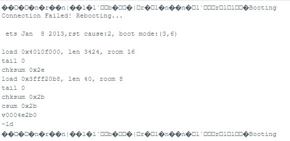
Okay, a few things…
when you post serial output, copy and paste the text from the serial monitor, and use triple backticks at the beginning and end, the same as when you post code. Don’t post screenshots.
you’d be har better using the native baud rate for your board as your serial baud rate, that way you’ll get less unintelligible stuff in your serial monitor.
Changing this…
to 74880 should probably do the trick.
you don’t have any Blynk connection commands in this sketch either. As you’re attempting to manage your own WiFi connection I would expect to see either Blynk.config(auth) or more sensibly Blynk.config(BLYNK_AUTH_TOKEN) and copy/paste the three lines of firmware configuration code from the Device info screen of the web console.
your sketch is failing because you aren’t managing to establish a connection to your WiFi network, not because of anything Blynk related. Either your ssid or pass are incorrect, or this connection method isn’t supported with the current ESP8266 core…
This WiFi connection code looks a little odd to me, and isn’t a structure that I’ve ever used.
Pete.
ok thanks for the comments. With regard top the blynk.config etc I have used this code for numerous other sketches and they all worked perfect until blynk 1 server was switched off.
So I guess I am no further forward with converting this?
Going back to where I started, I do have a working version with blynk edgent of this code, so I know for sure ssid, pasword, tokens and templates etc are all deffo correct.
All I was trying to do after chatting with you was eliminating the need to have all the edgent files loaded into the sketch folder, so is there an easier way to do this other than edgent?
TIA
Kev
Heres the working edgent version for info
// 4 Way Speaker Switch WiFi controller via Blynk  and push button
// Written by kevin Downes 17/04/2019
//
// 17/04/219 v2.0.0 - Release for Blynk V2.0  using Edgent OTA updates

#define BLYNK_TEMPLATE_ID "redacted"
#define BLYNK_TEMPLATE_NAME "redacted"
#define BLYNK_FIRMWARE_VERSION "redacted"

#define BLYNK_PRINT Serial

#define APP_DEBUG

// Uncomment your board, or configure a custom board in Settings.h
//#define USE_SPARKFUN_BLYNK_BOARD
//#define USE_NODE_MCU_BOARD
//#define USE_WITTY_CLOUD_BOARD
#define USE_WEMOS_D1_MINI
#include <Blynk.h>
#include "BlynkEdgent.h"

BlynkTimer timer;

int allSwitch;
bool pressed1 = false;
bool pressed2 = false;
bool pressed3 = false;
bool pressed4 = false;
bool resetFlag = true;  // TRUE when the hardware has been reset.

int RELAY12_pin = 5;   // Relay 1&2 pin D1
int RELAY34_pin = 4;   // Relay 3&4 pin D2
int RELAY56_pin = 0;   // Relay 5&6 pin D3
int RELAY78_pin = 2;   // Relay 7&8 pin D4
int Switch1_pin = 14;  // Digital pin for switch 1 input D5
int Switch2_pin = 12;  // Digital pin for switch 2 input D6
int Switch3_pin = 13;  // Digital pin for switch 3 input D7
int Switch4_pin = 15;  // Digital pin for switch 4 input D8

void setup() {

  Serial.begin(115200);
  delay(100);
  BlynkEdgent.begin();


  // set outputs for relay channels  - each pin fires a pair of relays
  pinMode(RELAY12_pin, OUTPUT);  //D1
  digitalWrite(RELAY12_pin, HIGH);
  pinMode(RELAY34_pin, OUTPUT);  //D2
  digitalWrite(RELAY34_pin, HIGH);
  pinMode(RELAY56_pin, OUTPUT);  //D3
  digitalWrite(RELAY56_pin, HIGH);
  pinMode(RELAY78_pin, OUTPUT);  //D4
  digitalWrite(RELAY78_pin, HIGH);

  //set input for each switch
  pinMode(Switch1_pin, INPUT);  //D5
  pinMode(Switch2_pin, INPUT);  //D6
  pinMode(Switch3_pin, INPUT);  //D7
  pinMode(Switch4_pin, INPUT);  //D8

  Blynk.syncVirtual(V80);
  Blynk.syncVirtual(V81);
  Blynk.syncVirtual(V82);
  Blynk.syncVirtual(V83);
  Blynk.syncVirtual(V126);

  if (resetFlag == true) {  // we need this to stop a switch detect after a reset/power failure
    pressed1 = true;
    pressed2 = true;
    pressed3 = true;
    pressed4 = true;
    resetFlag = false;
  }

  timer.setInterval(100, Switch1_detect);
  timer.setInterval(100, Switch2_detect);
  timer.setInterval(100, Switch3_detect);
  timer.setInterval(100, Switch4_detect);
  timer.setInterval(200, sigStrength);
}

void sigStrength() {
  long rssi = WiFi.RSSI();
  Blynk.virtualWrite(V90, rssi);
}


void Switch1_detect() {
  if (digitalRead(Switch1_pin) == 1 && pressed1 == false) {
    digitalWrite(RELAY12_pin, !digitalRead(RELAY12_pin));
    Blynk.virtualWrite(V40, !digitalRead(RELAY12_pin));
    Blynk.virtualWrite(V80, digitalRead(RELAY12_pin));
    pressed1 = true;
  } else if (digitalRead(Switch1_pin) == 0 && pressed1 == true) {
    pressed1 = false;
  }
}

void Switch2_detect() {
  if (digitalRead(Switch2_pin) == 1 && pressed2 == false) {
    digitalWrite(RELAY34_pin, !digitalRead(RELAY34_pin));
    Blynk.virtualWrite(V41, !digitalRead(RELAY34_pin));
    Blynk.virtualWrite(V81, digitalRead(RELAY34_pin));
    pressed2 = true;
  } else if (digitalRead(Switch2_pin) == 0 && pressed2 == true) {
    pressed2 = false;
  }
}

void Switch3_detect() {
  if (digitalRead(Switch3_pin) == 1 && pressed3 == false) {
    digitalWrite(RELAY56_pin, !digitalRead(RELAY56_pin));
    Blynk.virtualWrite(V42, !digitalRead(RELAY56_pin));
    Blynk.virtualWrite(V82, digitalRead(RELAY56_pin));
    pressed3 = true;
  } else if (digitalRead(Switch3_pin) == 0 && pressed3 == true) {
    pressed3 = false;
  }
}

void Switch4_detect() {
  if (digitalRead(Switch4_pin) == 1 && pressed4 == false) {
    digitalWrite(RELAY78_pin, !digitalRead(RELAY78_pin));
    Blynk.virtualWrite(V43, !digitalRead(RELAY78_pin));
    Blynk.virtualWrite(V83, digitalRead(RELAY78_pin));
    pressed4 = true;
  } else if (digitalRead(Switch4_pin) == 0 && pressed4 == true) {
    pressed4 = false;
  }
}

BLYNK_WRITE(V40)  // Runs every-time switch widget V40 is toggled.
{
  digitalWrite(RELAY12_pin, !digitalRead(RELAY12_pin));  // Toggle relay 1&2
  Blynk.virtualWrite(V80, digitalRead(RELAY12_pin));     // Store relay 1&2 state in V80
}

BLYNK_WRITE(V41)  // Runs every-time switch widget V41 is toggled.
{
  digitalWrite(RELAY34_pin, !digitalRead(RELAY34_pin));  // Toggle relay 3&4
  Blynk.virtualWrite(V81, digitalRead(RELAY34_pin));     // Store relay 3&4 state in V81
}

BLYNK_WRITE(V42)  // Runs every-time switch widget V42 is toggled.
{
  digitalWrite(RELAY56_pin, !digitalRead(RELAY56_pin));  // Toggle relay 5&6
  Blynk.virtualWrite(V82, digitalRead(RELAY56_pin));     // Store relay 5&6 state in V80
}

BLYNK_WRITE(V43)  // Runs every-time switch widget V43 is toggled.
{
  digitalWrite(RELAY78_pin, !digitalRead(RELAY78_pin));  // Toggle relay 7&8
  Blynk.virtualWrite(V83, digitalRead(RELAY78_pin));     // Store relay 7&8 state in V83
}

BLYNK_WRITE(V80) {
  int V80_Data = param.asInt();
  digitalWrite(RELAY12_pin, V80_Data);
  Blynk.virtualWrite(V40, !digitalRead(RELAY12_pin));
}

BLYNK_WRITE(V81) {
  int V81_Data = param.asInt();
  digitalWrite(RELAY34_pin, V81_Data);
  Blynk.virtualWrite(V41, !digitalRead(RELAY34_pin));
}

BLYNK_WRITE(V82) {
  int V82_Data = param.asInt();
  digitalWrite(RELAY56_pin, V82_Data);
  Blynk.virtualWrite(V42, !digitalRead(RELAY56_pin));
}

BLYNK_WRITE(V83) {
  int V83_Data = param.asInt();
  digitalWrite(RELAY78_pin, V83_Data);
  Blynk.virtualWrite(V43, !digitalRead(RELAY78_pin));
}

BLYNK_WRITE(V126) {
  int V126_Data = param.asInt();
  allSwitch = V126_Data;
  Blynk.virtualWrite(V127, allSwitch);
}

BLYNK_WRITE(V127)  // Lets switch ALL Speakers on or off.
{
  if (allSwitch == 0) {                                  // switch on
    digitalWrite(RELAY12_pin, 0);                        // Toggle relay 1&2
    Blynk.virtualWrite(V40, !digitalRead(RELAY12_pin));  // Update widget
    Blynk.virtualWrite(V80, digitalRead(RELAY12_pin));   // Store relay 1&2 state in V80
    digitalWrite(RELAY34_pin, 0);                        // Toggle relay 3&4
    Blynk.virtualWrite(V41, !digitalRead(RELAY34_pin));  // Update widget
    Blynk.virtualWrite(V81, digitalRead(RELAY34_pin));   // Store relay 3&4 state in V81
    digitalWrite(RELAY56_pin, 0);                        // Toggle relay 5&6
    Blynk.virtualWrite(V42, !digitalRead(RELAY56_pin));  // Update widget
    Blynk.virtualWrite(V82, digitalRead(RELAY56_pin));   // Store relay 5&6 state in V82
    digitalWrite(RELAY78_pin, 0);                        // Toggle relay 7&8
    Blynk.virtualWrite(V43, !digitalRead(RELAY78_pin));  // Update widget
    Blynk.virtualWrite(V83, digitalRead(RELAY78_pin));   // Store relay 7&8 state in V83
    allSwitch = 1;
    Blynk.virtualWrite(V126, allSwitch);
  } else {                                               //Switch OFF
    digitalWrite(RELAY12_pin, 1);                        // Toggle relay 1&2
    Blynk.virtualWrite(V40, !digitalRead(RELAY12_pin));  // Update widget
    Blynk.virtualWrite(V80, digitalRead(RELAY12_pin));   // Store relay 1&2 state in V80
    digitalWrite(RELAY34_pin, 1);                        // Toggle relay 3&4
    Blynk.virtualWrite(V41, !digitalRead(RELAY34_pin));  // Update widget
    Blynk.virtualWrite(V81, digitalRead(RELAY34_pin));   // Store relay 3&4 state in V81
    digitalWrite(RELAY56_pin, 1);                        // Toggle relay 5&6
    Blynk.virtualWrite(V42, !digitalRead(RELAY56_pin));  // Update widget
    Blynk.virtualWrite(V82, digitalRead(RELAY56_pin));   // Store relay 5&6 state in V82
    digitalWrite(RELAY78_pin, 1);                        // Toggle relay 7&8
    Blynk.virtualWrite(V43, !digitalRead(RELAY78_pin));  // Update widget
    Blynk.virtualWrite(V83, digitalRead(RELAY78_pin));   // Store relay 7&8 state in V83
    allSwitch = 0;
    Blynk.virtualWrite(V126, allSwitch);
  }
}
void loop() {
  BlynkEdgent.run();
  timer.run();
}
Serial output…
    ___  __          __
   / _ )/ /_ _____  / /__
  / _  / / // / _ \/  '_/
 /____/_/\_, /_//_/_/\_\
        /___/ v1.2.0 on ESP8266

 #StandWithUkraine    https://bit.ly/swua


----------------------------------------------------
 Device:    Blynk 4 way speaker switch-J1PC
 Firmware:  0.1.0 (build Jul  6 2023 09:32:04)
 Token:     pt5M - •••• - •••• - ••••
 Platform:  ESP8266 @ 80MHz
 Boot ver:  31
 SDK:       2.2.2-dev(38a443e)
 ESP Core:  3.1.2
 Flash:     16384K
 Free mem:  29256
----------------------------------------------------

>[467] INIT => CONNECTING_NET
[471] Hold the button for 10 seconds to reset configuration...
[480] Connecting to WiFi: BThub5-JSR3
[4541] Using Dynamic IP: 192.168.1.119
[4541] CONNECTING_NET => CONNECTING_CLOUD
[4654] Current time: Thu Jul  6 08:32:26 2023
[4654] Connecting to blynk.cloud:443
[5526] Ready (ping: 11ms).
[5608] CONNECTING_CLOUD => RUNNING
I don’t see how that is possible. Every Blynk Legacy or IoT sketch needs either a Blynk.begin or Blynk.config command to tell it how to connect to the Blynk server. Your has neither.
I suspect that upgrading to the latest ESP8266 core has broken your WiFi connect routine, but there are plenty of examples on better structured routines.
Yes, just look at the non-Edgent examples in the library.
Pete.
OK pete will do
cheers
kev
Hi Pete,
I have now got the legacy code working perfect with Blynk2.0 using ESP8266 via Wifi. Super!!
Next question is how would I modified this sketch to do updates over the air. Are there several different ways to do this?
The code I showed you before that you weren’t familiar with used to allow the Arduino IDE to see a wifi device as a port and then do an update just using that port and the upload button.
Once I have this sorted I promise I am out of your hair!!!
TIA
Kev
Here’s the working code with blynk 2.0 and Wifi
// 4 Way Speaker Switch WiFi controller via Blynk  and push button
// Written by kevin Downes 17/04/2019
//
// 17/04/219 v1.0.0 - Release
// 06/07/2023 V2.0.0 - Mod to work with Blynk 2.0 and WiFi

#define BLYNK_TEMPLATE_ID "redacted"
#define BLYNK_TEMPLATE_NAME "redacted"
#define BLYNK_AUTH_TOKEN "redacted"
/* Comment this out to disable prints and save space */
#define BLYNK_PRINT Serial

#include <ESP8266WiFi.h>
#include <BlynkSimpleEsp8266.h>

// Your WiFi credentials.
char ssid[] = "redacted";
char pass[] = "redacted";

BlynkTimer timer;

int allSwitch;
bool pressed1 = false;
bool pressed2 = false;
bool pressed3 = false;
bool pressed4 = false;
bool resetFlag = true;  // TRUE when the hardware has been reset.

int RELAY12_pin = 5;      // Relay 1&2 pin D1
int RELAY34_pin = 4;      // Relay 3&4 pin D2
int RELAY56_pin = 0;      // Relay 5&6 pin D3
int RELAY78_pin = 2;      // Relay 7&8 pin D4
int Switch1_pin = 14;     // Digital pin for switch 1 input D5
int Switch2_pin = 12;     // Digital pin for switch 2 input D6
int Switch3_pin = 13;     // Digital pin for switch 3 input D7
int Switch4_pin = 15;     // Digital pin for switch 4 input D8

void setup() {

  // put your setup code here, to run once:
  Serial.begin(9600);
  Blynk.begin(BLYNK_AUTH_TOKEN, ssid, pass);

  // set outputs for relay channels  - each pin fires a pair of relays
  pinMode(RELAY12_pin, OUTPUT); //D1
  digitalWrite(RELAY12_pin, HIGH);
  pinMode(RELAY34_pin, OUTPUT); //D2
  digitalWrite(RELAY34_pin, HIGH);
  pinMode(RELAY56_pin, OUTPUT); //D3
  digitalWrite(RELAY56_pin, HIGH);
  pinMode(RELAY78_pin, OUTPUT); //D4
  digitalWrite(RELAY78_pin, HIGH);

  //set input for each switch
  pinMode(Switch1_pin, INPUT); //D5
  pinMode(Switch2_pin, INPUT); //D6
  pinMode(Switch3_pin, INPUT); //D7
  pinMode(Switch4_pin, INPUT); //D8

  Blynk.syncVirtual(V80);
  Blynk.syncVirtual(V81);
  Blynk.syncVirtual(V82);
  Blynk.syncVirtual(V83);
  Blynk.syncVirtual(V126);

  if (resetFlag == true) { // we need this to stop a switch detect after a reset/power failure
    pressed1 = true;
    pressed2 = true;
    pressed3 = true;
    pressed4 = true;
    resetFlag = false;
  }

  timer.setInterval(100, Switch1_detect);
  timer.setInterval(100, Switch2_detect);
  timer.setInterval(100, Switch3_detect);
  timer.setInterval(100, Switch4_detect);
  timer.setInterval(250, sigStrength);
}

void sigStrength()
{
  long rssi = WiFi.RSSI();
  Blynk.virtualWrite(V90, rssi);
 }


void Switch1_detect()
{
  if (digitalRead(Switch1_pin) == 1 && pressed1 == false) {
    digitalWrite(RELAY12_pin, !digitalRead(RELAY12_pin));
    Blynk.virtualWrite(V40, !digitalRead(RELAY12_pin));
    Blynk.virtualWrite(V80, digitalRead(RELAY12_pin));
    pressed1 = true;
  }
  else if (digitalRead(Switch1_pin) == 0 && pressed1 == true) {
    pressed1 = false;
  }
}

void Switch2_detect()
{
  if (digitalRead(Switch2_pin) == 1 && pressed2 == false) {
    digitalWrite(RELAY34_pin, !digitalRead(RELAY34_pin));
    Blynk.virtualWrite(V41, !digitalRead(RELAY34_pin));
    Blynk.virtualWrite(V81, digitalRead(RELAY34_pin));
    pressed2 = true;
  }
  else if (digitalRead(Switch2_pin) == 0 && pressed2 == true) {
    pressed2 = false;
  }
}

void Switch3_detect()
{
  if (digitalRead(Switch3_pin) == 1 && pressed3 == false) {
    digitalWrite(RELAY56_pin, !digitalRead(RELAY56_pin));
    Blynk.virtualWrite(V42, !digitalRead(RELAY56_pin));
    Blynk.virtualWrite(V82, digitalRead(RELAY56_pin));
    pressed3 = true;
  }
  else if (digitalRead(Switch3_pin) == 0 && pressed3 == true) {
    pressed3 = false;
  }
}

void Switch4_detect()
{
  if (digitalRead(Switch4_pin) == 1 && pressed4 == false) {
    digitalWrite(RELAY78_pin, !digitalRead(RELAY78_pin));
    Blynk.virtualWrite(V43, !digitalRead(RELAY78_pin));
    Blynk.virtualWrite(V83, digitalRead(RELAY78_pin));
    pressed4 = true;
  }
  else if (digitalRead(Switch4_pin) == 0 && pressed4 == true) {
    pressed4 = false;
  }
}

BLYNK_WRITE(V40)  // Runs every-time switch widget V40 is toggled.
{
  digitalWrite(RELAY12_pin, !digitalRead(RELAY12_pin));        // Toggle relay 1&2
  Blynk.virtualWrite(V80, digitalRead(RELAY12_pin)); // Store relay 1&2 state in V80
}

BLYNK_WRITE(V41)  // Runs every-time switch widget V41 is toggled.
{
  digitalWrite(RELAY34_pin, !digitalRead(RELAY34_pin));        // Toggle relay 3&4
  Blynk.virtualWrite(V81, digitalRead(RELAY34_pin)); // Store relay 3&4 state in V81
}

BLYNK_WRITE(V42)  // Runs every-time switch widget V42 is toggled.
{
  digitalWrite(RELAY56_pin, !digitalRead(RELAY56_pin));        // Toggle relay 5&6
  Blynk.virtualWrite(V82, digitalRead(RELAY56_pin)); // Store relay 5&6 state in V80
}

BLYNK_WRITE(V43)  // Runs every-time switch widget V43 is toggled.
{
  digitalWrite(RELAY78_pin, !digitalRead(RELAY78_pin));        // Toggle relay 7&8
  Blynk.virtualWrite(V83, digitalRead(RELAY78_pin)); // Store relay 7&8 state in V83
}

BLYNK_WRITE(V80)
{
  int V80_Data = param.asInt();
  digitalWrite(RELAY12_pin, V80_Data);
  Blynk.virtualWrite(V40, !digitalRead(RELAY12_pin));
}

BLYNK_WRITE(V81)
{
  int V81_Data = param.asInt();
  digitalWrite(RELAY34_pin, V81_Data);
  Blynk.virtualWrite(V41, !digitalRead(RELAY34_pin));
}

BLYNK_WRITE(V82)
{
  int V82_Data = param.asInt();
  digitalWrite(RELAY56_pin, V82_Data);
  Blynk.virtualWrite(V42, !digitalRead(RELAY56_pin));
}

BLYNK_WRITE(V83)
{
  int V83_Data = param.asInt();
  digitalWrite(RELAY78_pin, V83_Data);
  Blynk.virtualWrite(V43, !digitalRead(RELAY78_pin));
}

BLYNK_WRITE(V126)
{
  int V126_Data = param.asInt();
  allSwitch = V126_Data;
  Blynk.virtualWrite(V127, allSwitch);
}

BLYNK_WRITE(V127)  // Lets switch ALL Speakers on or off.
{
  if (allSwitch == 0) { // switch on
    digitalWrite(RELAY12_pin, 0);        // Toggle relay 1&2
    Blynk.virtualWrite(V40, !digitalRead(RELAY12_pin));// Update widget
    Blynk.virtualWrite(V80, digitalRead(RELAY12_pin)); // Store relay 1&2 state in V80
    digitalWrite(RELAY34_pin, 0);        // Toggle relay 3&4
    Blynk.virtualWrite(V41, !digitalRead(RELAY34_pin));// Update widget
    Blynk.virtualWrite(V81, digitalRead(RELAY34_pin)); // Store relay 3&4 state in V81
    digitalWrite(RELAY56_pin, 0);        // Toggle relay 5&6
    Blynk.virtualWrite(V42, !digitalRead(RELAY56_pin));// Update widget
    Blynk.virtualWrite(V82, digitalRead(RELAY56_pin)); // Store relay 5&6 state in V82
    digitalWrite(RELAY78_pin, 0);        // Toggle relay 7&8
    Blynk.virtualWrite(V43, !digitalRead(RELAY78_pin));// Update widget
    Blynk.virtualWrite(V83, digitalRead(RELAY78_pin)); // Store relay 7&8 state in V83
    allSwitch = 1;
    Blynk.virtualWrite(V126, allSwitch);
  }
  else
  { //Switch OFF
    digitalWrite(RELAY12_pin, 1);                      // Toggle relay 1&2
    Blynk.virtualWrite(V40, !digitalRead(RELAY12_pin));// Update widget
    Blynk.virtualWrite(V80, digitalRead(RELAY12_pin)); // Store relay 1&2 state in V80
    digitalWrite(RELAY34_pin, 1);                      // Toggle relay 3&4
    Blynk.virtualWrite(V41, !digitalRead(RELAY34_pin));// Update widget
    Blynk.virtualWrite(V81, digitalRead(RELAY34_pin)); // Store relay 3&4 state in V81
    digitalWrite(RELAY56_pin, 1);                      // Toggle relay 5&6
    Blynk.virtualWrite(V42, !digitalRead(RELAY56_pin));// Update widget
    Blynk.virtualWrite(V82, digitalRead(RELAY56_pin)); // Store relay 5&6 state in V82
    digitalWrite(RELAY78_pin, 1);                      // Toggle relay 7&8
    Blynk.virtualWrite(V43, !digitalRead(RELAY78_pin));// Update widget
    Blynk.virtualWrite(V83, digitalRead(RELAY78_pin)); // Store relay 7&8 state in V83
    allSwitch = 0;
    Blynk.virtualWrite(V126, allSwitch);
  }
}
void loop() {
  Blynk.run();
  timer.run();

}
You have two options:
use Arduino OTA in exactly the same way that you did before. Note that with more recent versions of the ESP8266 core the ArduinoOTA.begin() must come after the internet connection has been established, and as you are now using Blynk.begin() to do this that means that it must appear after Blynk.begin().
use.Blynk.Air by inserting the ESP8266 version of the minimal code into your existing sketch.
Pete.