i am doing the same thing with a 4ch relay to control it via app and physical push button.
However i am able to control the relays via blynk app, but the physical buttons are not doing anything, i guess my button connection ( hardware side ) is wrong can u please help with a diagram how you connected the physical button.?
As the topic that you tagged this on to was three years old, I’ve moved your question to its own topic.
Please post your code (correctly formatted) along with details of the hardware you’re using and how you’ve wired it up, including how your buttons are wired.
Pete.
1 Like
Here is the Code which i Uploaded to the Nodemcu. Got it from a post in Blynk Community just changed the Auth & wifi Credentials.
#define BLYNK_PRINT Serial


#include <ESP8266WiFi.h>
#include <BlynkSimpleEsp8266.h>

// You should get Auth Token in the Blynk App.
// Go to the Project Settings (nut icon).
char auth[] = "xxxxxxxxxx";

// Your WiFi credentials.
// Set password to "" for open networks.
char ssid[] = "xxxx";
char pass[] = "xxxxxxx";

// Set your LED and physical button pins here
const int ledPin1 = 12;
const int ledPin2 = 13;
const int ledPin3 = 14;
const int ledPin4 = 15;
const int btnPin1 = 5;
const int btnPin2 = 4;
const int btnPin3 = 9;
const int btnPin4 = 1;

BlynkTimer timer;
void checkPhysicalButton();

int led1State = LOW;
int btn1State = HIGH;

int led2State = LOW;
int btn2State = HIGH;

int led3State = LOW;
int btn3State = HIGH;

int led4State = LOW;
int btn4State = HIGH;

// Every time we connect to the cloud...
BLYNK_CONNECTED() {
  // Request the latest state from the server
  Blynk.syncVirtual(V12);
  Blynk.syncVirtual(V13);
  Blynk.syncVirtual(V14);
  Blynk.syncVirtual(V15);

  // Alternatively, you could override server state using:
  //Blynk.virtualWrite(V12, led1State);
  //Blynk.virtualWrite(V13, led2State);
  //Blynk.virtualWrite(V14, led3State);
  //Blynk.virtualWrite(V15, led4State);

}

// When App button is pushed - switch the state
BLYNK_WRITE(V12) {
  led1State = param.asInt();
  digitalWrite(ledPin1, led1State);
}

 BLYNK_WRITE(V13) {
  led2State = param.asInt();
  digitalWrite(ledPin2, led2State);
 }
BLYNK_WRITE(V14) {
  led3State = param.asInt();
  digitalWrite(ledPin3, led3State);
}
BLYNK_WRITE(V15) {
  led4State = param.asInt();
  digitalWrite(ledPin4, led4State);
}

void checkPhysicalButton()
{
  if (digitalRead(btnPin1) == LOW) {
    // btn1State is used to avoid sequential toggles
    if (btn1State != LOW) {

      // Toggle LED state
      led1State = !led1State;
      digitalWrite(ledPin1, led1State);

      // Update Button Widget
      Blynk.virtualWrite(V12, led1State);
    }
    btn1State = LOW;
  } else {
    btn1State = HIGH;
  }

  if (digitalRead(btnPin2) == LOW) {
    // btnState is used to avoid sequential toggles
    if (btn2State != LOW) {

      // Toggle LED state
      led2State = !led2State;
      digitalWrite(ledPin2, led2State);

      // Update Button Widget
      Blynk.virtualWrite(V13, led2State);
    }
    btn2State = LOW;
  } else {
    btn2State = HIGH;
  }

  if (digitalRead(btnPin3) == LOW) {
    // btnState is used to avoid sequential toggles
    if (btn3State != LOW) {

      // Toggle LED state
      led3State = !led3State;
      digitalWrite(ledPin3, led3State);

      // Update Button Widget
      Blynk.virtualWrite(V14, led3State);
    }
    btn3State = LOW;
  } else {
    btn3State = HIGH;
  }

  if (digitalRead(btnPin4) == LOW) {
    // btnState is used to avoid sequential toggles
    if (btn4State != LOW) {

      // Toggle LED state
      led4State = !led4State;
      digitalWrite(ledPin4, led4State);

      // Update Button Widget
      Blynk.virtualWrite(V15, led4State);
    }
    btn4State = LOW;
  } else {
    btn4State = HIGH;
  }
}

void setup()
{
  // Debug console
  Serial.begin(9600);

  Blynk.begin(auth, ssid, pass);
  // You can also specify server:
  //Blynk.begin(auth, ssid, pass, "blynk-cloud.com", 8442);
  //Blynk.begin(auth, ssid, pass, IPAddress(192,168,1,100), 8442);

  pinMode(ledPin1, OUTPUT);
  pinMode(btnPin1, INPUT_PULLUP);
  digitalWrite(ledPin1, led1State);


  pinMode(ledPin2, OUTPUT);
  pinMode(btnPin2, INPUT_PULLUP);
  digitalWrite(ledPin2, led2State);


  pinMode(ledPin3, OUTPUT);
  pinMode(btnPin3, INPUT_PULLUP);
  digitalWrite(ledPin3, led3State);


  pinMode(ledPin4, OUTPUT);
  pinMode(btnPin4, INPUT_PULLUP);
  digitalWrite(ledPin4, led4State);

  // Setup a function to be called every 100 ms
  timer.setInterval(500L, checkPhysicalButton);
}

void loop()
{
  Blynk.run();
  timer.run();
}
After this connected the Relays to D5 / GPIO14, D6 / GPIO12, D7 / 13, D8 / 15.
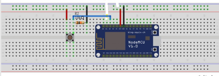
then connected the Physical push buttons to the following pins - D1 / GPIO5 , D2 / GPIO4 , SD1 / GPIO10, SD2 / GPIO9 using a 10kohm resistor connected to ground and gave the other pin of button to 3.3v ( both taken form nodemcu itself).
the Physical Pin connection of buttons is something like the image attached, but doing the same with 4 buttons
did you have a common ground for both the Nodemcu and the Relay module?
1 Like
i gave the vin and ground connection to the relay board via nodemcu 3.3v and gnd connections respectively.
and nodemcu is powered from my phones micro-usb charger.
just a part of debugging could you connect LED’s to any of the relay pin say D5 and check if your logic works fine.
Secondly try powering the relay board with Vin pin of NodeMcu rather than 3.3v
1 Like
The relay board is working perfectly fine when I toggle the state from blynk app, i can see the relays light and hear the relays tick.
The only problem I’m facing is the physical push (hardware) buttons are not doing anything!
Despite me asking you to correctly format your code, you didn’t.
I’ve corrected it for you this time, but in future incorrectly formatted code will be deleted from your posts.
The code must be preceded and followed by three backticks characters like this:
```
Pete.
1 Like
Sorry for that… And thanks for formatting it…!
You’ve connected your physical button so that one side is connected to the digital pin, and the other side is connected to 3.3v
The side of the switch that’s connected to the digital pin is being pulled LOW by the 10k resistor to prevent it floating in an intermediate state (more on that later).
This means that when you press the physical button, the digital pin will be pulled HIGH.
Your code had defined the digital pins for the physical buttons as INPUT_PULLUPs, meaning that they’ll be pulled HIGH by default, so external pull-up resistors aren’t needed to prevent them from floating, and all of your code is looking for a LOW signal from the switch to actuate your relays.
If you throw away the pull-down resistors and connect the other side of the switch to GND rather than 3.3v it should work as desired.
However, you should also read this:
Pete.
Hey Sorry for the delayed reply for some reason my esp8266 went bad so had to order a new one and finally it came and tried your solution on it and man it worked.
And As you suggested the thing worked perfectly by removing the resistors.
However only two of my Butoons are working the other two buttons connected to GPIO 10 & 9 or S3 , S4 are not working for some reason.
Try clicking the link I provided about GPIO pins and see what it says about pins 6 to 11.
Pete.
I don’t think you need to be rude when one needs help. Should we than not use Blynk and find another App with better support???
You are new here, so are probably unaware of the rules regarding posting. Good support also requires good questions and participating users willing to read, listen and learn. @PeteKnight was not rude, nor did he do anything worthy of your unnecessary critiquing.
Feel free to go wherever you wish, but good luck finding better support than from the members of this forum.
3 Likes
Support for the free version of Blynk is provided by other users (like myself) who volunteer their time and knowledge to help others.
If you think that some or all of my comments that enabled @swapnilkute2777 to resolve his problem were rude or unhelpful then I’d suggest you hit the ‘Flag’ button so that the issue can be bought to the attention of Blynk staff and appropriate action taken.
Pete.
2 Likes
With attitude like yours you are running down this company and yes I will not be using Blynk for my future Industrial projects.
I’m pretty sure @PeteKnight nor @Gunner is affiliated with Blynk. - They donate their spare time to help users on the forum.
Both of whom are very knowledgeable.
3 Likes
@firdosh Barely two posts in and already making friends ![]() We will miss you.
We will miss you.
Yes, and thank you @JustBertC I am just a long term Blynk forum volunteer… and still learning as I go.
And like many of us regulars, we just have fun helping as best as we can… even if we have to resort to some “tough love” teaching methods with the “problem children” ![]()
1 Like
“Industrial projects” implies that this is a commercial application, which is strictly forbidden for the free version of Blynk - which is the version supported via this forum.
If you pay $166 per month the you’ll get email support within 48 hours from Blynk staff.
To paraphrase a common saying - if you pay nothing then you get rude monkeys like @Gunner and myself.
Good luck find anything that comes close to the functionality of Blynk.
Pete.
2 Likes
Yup… Give this monkey crap, get ![]()
![]() right back
right back ![]()
Notice how he didn’t get snarky in “his” topic when looking for answers ![]()
3 Likes