I’m confused about your use of HIGH and LOW when working with this relay.
The code above is saying “if the widget switch is in the off position then set the relay pin LOW”.
From that I would deduce that a LOW signal turns your relay load off.
But if that is the case then this line of code:
is turning the relay in at startup.
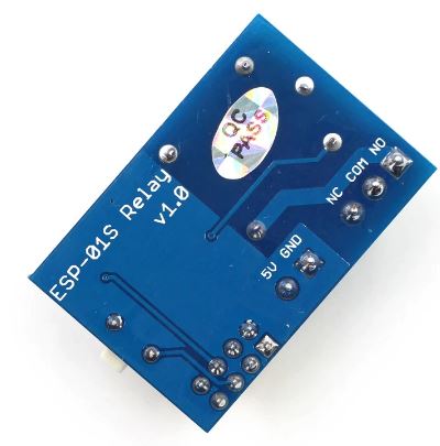
The load contacts of your relay have three connections - common, normally open and normally closed.
I suspect that you are using the wrong set of contacts for the realty’s load, and that you have to replace all of your LOW commands with HIGH commands and vice-versa.
J’ai pris un ESP-01s neuf dont je n’ai rien téléversé dedans, et lors de sa mise sous tension, le même phénomène se passe (1 battement du relai qui se ferme et s’ouvre).
@AGB44 It’s very difficult to help you if you don’t provide more information, in a structured way.
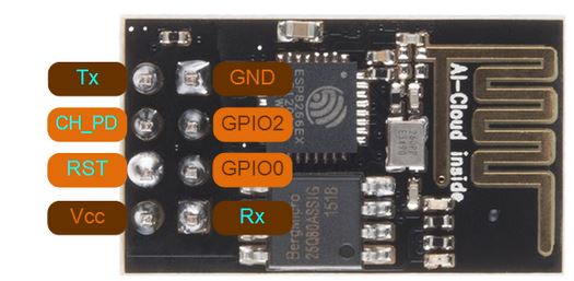
Which relay contacts are you using, and what is the status of these contacts when no power is applied to the system?
Does writing a HIGH signal to GPIO0 make these contacts open or close?
Does writing a HIGH signal to GPIO0 energise the coil of the relay?
Mais cela dès la mise sous tension actionne mon relais pendant 6 secondes avant de retomber.
Le fait de mettre
digitalWrite(0,HIGH);
Permet au relais de ne plus avoir une impulsion au bout de 6 secondes.
Mon problème restant est cette impulsion instantanée des la remise sous tension.
Désolé de ne pas être structuré comme il le faudrait.
Concernant ceci :
“J’ai pris un ESP-01s neuf dont je n’ai rien téléversé dedans, et lors de sa mise sous tension, le même phénomène se passe (1 battement du relai qui se ferme et s’ouvre)”
Mon problème est-t-il vraiment lié au programme ?
@AGB44 you seem reluctant to provide straight answers to my questions about your relay board.
Normally, it’s recommended to avoid using GPIO0 for this type of application, but I’ve seen this pin used very successfully in the past, and I’m fairly confident that you could get this working correctly. However, as none of has the same hardware as you, we are reliant on you providing us with information about the hardware, but you aren’t doing that.
Je fais pourtant pour le mieux, mais ce domaine n’est pas de ma spécialité.
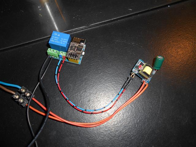
Je te transmets les photos des produits acheté ainsi que le raccordement effectué
Étant limité dans les pièces jointes, je vais essayé de te les transmettre sur plusieurs messages.
J’ai alimenté via le module adaptateur 230VAC/5VCC le module relai (broches VCC/GND) et me sert des broches NO/COM de mon contact inverseur du relai. Ensuite, j’incère le module ESP-01s sur le connecteur jaune du module relai.
Cela t’aide, ou il te faut d’autres éléments ?
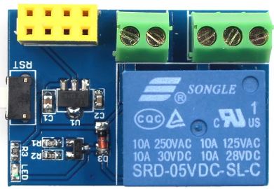
Le relais est composé d’une bobine alimentée sous 5 VCC par le module, et de contacts secs inverseurs, qui ne sont reliés à la bobine que mécaniquement. Je peux donc raccorder sur les contacts du relai des récepteurs allant jusqu’à 10 ampères sous 250 volts alternatif.
Donc si la bobine du relai n’est pas alimentée, le contact NO-COM est ouvert, et le contact NC-COM est fermé. Si la bobine du relai est alimentée par du 5 VCC, le contact NO-COM est fermé, et le contact NC-COM est ouvert. Donc l’écriture alimente la bobine du relai, mais en aucun cas les contacts.
Once again, a very long response, which explains how a relay works (something I’m already aware of) but which doesn’t answer either of the two questions I asked.
I’ll take a step back from this discussion, as it’s going nowhere.
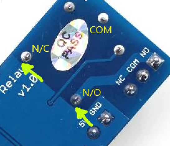
I was just taking a closer look at the layout of this board.
The Normally Open and Normally Closed load pins on the relay appear to be around 0.5mm away from the 5v groundplane, with no air gaps (yellow arrows in the image below)…
I can understand the motivation for not cutting air gaps into the PCB, as this costs money, but I don’t understand why they’d run the groundplane so close to these pins that are going to be at mains potential.
Maybe this was a project they gave to the trainee PCB designer