The odd thing is in both cases there’s nothing on the serial monitor but one of the sketches executes, connects to the server and starts updating the sensors’data. In the other case nothing is going on.
Good indication whether the code is working is if the OLED lights up which in the 3G code version doesn’t happen although the 3G modem service menu shows ESP01 is connected.
I’m catching several WiFi signals with my tablet. Is it possible that the WiFi signals are interfering and preventing sketch to execute?
According to the local router WiFi analyzer:
Signal(dBm) Signal(%)
1 0 100
2 -32 100
1 is local router
2 is 3G modem
You said you were using a NodeMCU, not an ESP-01
You need to share the contents of your stationDefines.h file.
Pete.
It’s NodeMCU but in the list of connected to the 3G modem devices it’s listed as ESP-01E541.
stationDefines.h:
/* Automatic Control Parameters Definition */
#define DRY_SOIL      66
#define WET_SOIL      85
#define COLD_TEMP     12
#define HOT_TEMP      25
#define TIME_PUMP_ON  15
#define TIME_LAMP_ON  15

/* TIMER */
#define READ_BUTTONS_TM   1L  // definitions in seconds
#define READ_SOIL_TEMP_TM 2L
#define READ_SOIL_HUM_TM  10L
#define READ_AIR_DATA_TM  2L
#define SEND_UP_DATA_TM   10L
#define AUTO_CTRL_TM      60L

/* OLED */
boolean turnOffOLED = 1;
#define SHOW_SET_UP   30

/* DHT22*/
#define DHTPIN D3
#define DHTTYPE DHT22
float airHum = 0;
float airTemp = 0;

/* Soil Moister */
#define soilMoisterPin A0
#define soilMoisterVcc D8
int soilMoister = 0;

/* DS18B20 Temperature Sensor */
#define ONE_WIRE_BUS 14 // DS18B20 on NodeMCU pin D5 corresponds to GPIO 014 on Arduino
float soilTemp;

/* Relays */
#define PUMP_PIN D6              //PUMP (Red LED)
#define LAMP_PIN D7              //LAMP (Green LED)
boolean pumpStatus = 0;
boolean lampStatus = 0;

/* Buttons */
#define PUMP_ON_BUTTON D9        //push-button PUMP (Red) D9 Rx
#define LAMP_ON_BUTTON D10      //push-button LAMP (Green) D10 Tx
#define SENSORS_READ_BUTTON D4   //push-button SENSOR (yellow)
What changes will have to be made in the code if I remove the local WiFi router from the equation thus connectiing directly to the web?
What Custom IP should I input when signing into Blynk? My public IP or the No-Ip one?
Where is this function?
How would this connection direct to the web work, I don’t understand what you are suggesting.
The reason that your serial monitor isn’t working is because you’re using GPIO3 (Serial Rx, pin D9) and GPIO1 (Serial Tx, pin D10) for physical buttons in your sketch.
If you’re using this many pins then you should be thinking about an ESP32.
Pete.
Where is this function?
It’s located in generalFunctions.h:
/***************************************************
* Wait Button to be pressed a defined time in seconds
****************************************************/
void waitButtonPress (int waitTime)
{
  long startTiming = millis();
  while (debounce(SENSORS_READ_BUTTON))
  {
    if ((millis()-startTiming) > (waitTime*1000)) break;
  }
}

/***************************************************
* Starting Timers
****************************************************/
void startTimers(void)
{
  timer.setInterval(READ_BUTTONS_TM*1000, readLocalCmd);
  timer.setInterval(READ_SOIL_TEMP_TM*1000, getSoilTempData);
  timer.setInterval(READ_AIR_DATA_TM*1000, getDhtData);
  timer.setInterval(READ_SOIL_HUM_TM*1000, getSoilMoisterData);
  timer.setInterval(SEND_UP_DATA_TM*1000, sendUptime);
  timer.setInterval(AUTO_CTRL_TM*1000, autoControlPlantation);
  //timer.setInterval(DISPLAY_DATA_TM*1000, displayData);
}

/***************************************************
* Debouncing a key
****************************************************/
boolean debounce(int pin)
{
  boolean state;
  boolean previousState;
  const int debounceDelay = 30;

  previousState = digitalRead(pin);
  for(int counter=0; counter< debounceDelay; counter++)
  {
    delay(1);
    state = digitalRead(pin);
    if(state != previousState)
    {
      counter = 0;
      previousState = state;
    }
  }
  return state;
}
I assigned those buttons (which I don’t really need) to different pins and now I get this on the serial monitor:
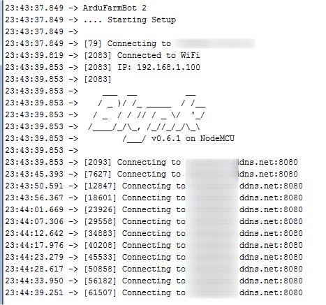
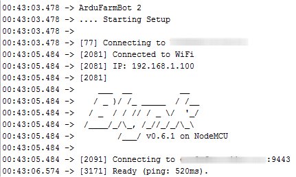
IP: 192.168.1.100 is the IP assigned to theNodeMCU by the 3G router.
I finally got it working by changing port 8080 in the sketch to 9443.
I could log into Blynk only when the Custom port was 9443 but not 8080 although I don’t understand why.
Can I now clone my existing local WiFi server project with the inputs and auth token from the 3G server project (I used only one gauge for testing) or I’ll have to do everything manually one more time?
Probably the ISP of your mobile router’s SIM card is blocking Blynk traffic on that port.
Sorry, I don’t understand the question. What are you trying to achieve?
Pete.
Before I attempted 3G connection I had my Blynk server project running/connecting to my local WiFi router. My question is can I duplicate/clone this project but now make it 3G connected or I have to create a new blank project with new auth token and recreate step by step everything one more time?
Is it your intention to have two copies of the project running at the same time?
If not, then why can’t you use the existing project?
It is obviously possible to clone the project, but if you are having two devices - one in one location and the other in another - then it may be better to have one project with two devices and maybe use the Tabs widget.
I find switching between projects a little cumbersome.
Pete.
Is it your intention to have two copies of the project running at the same time?
If not, then why can’t you use the existing project?
I sorted this out already.
I’m sorry for all these questions but I’m new to this and still learning how the things work.
The other thing I would like to implement to my greenhouse project is video streaming or at least taking stills. I was able to complete a project where ESP32-CAM was taking pictures and sending them to Blynk local server (local WiFi). This is the code I used:
//Viral Science www.youtube.com/c/viralscience www.viralsciencecreativity.com
//Blynk ESP32 CAM Simple Monitor System
//While Uploading Code on ESP32 Board 1, comment the lines number: 17,36 and Uncomment lines: 16,35
//While Uploading Code on ESP32 Board 2, comment the lines number: 16,35 and Uncomment lines: 17,36
#include "esp_camera.h"
#include <WiFi.h>
#include <WiFiClient.h>
#include <BlynkSimpleEsp32.h>
// Select camera model
#define CAMERA_MODEL_AI_THINKER // Has PSRAM
#include "camera_pins.h"
#define PHOTO 14 //ESP32 CAM 1
//#define PHOTO 15 //ESP32 CAM 2
#define LED 4
const char* ssid = ""; //wifi name
const char* password = ""; //password
char auth[] = ""; //Auth Code sent by Blynk
String local_IP;
int count = 0;
void startCameraServer();
void takePhoto()
{
digitalWrite(LED, HIGH);
delay(200);
uint32_t randomNum = random(50000);
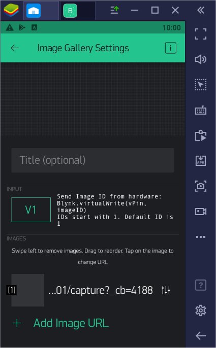
Serial.println("http://"+local_IP+"/capture?_cb="+ (String)randomNum);
Blynk.setProperty(V1, "urls", "http://"+local_IP+"/capture?_cb="+(String)randomNum); //ESP32 CAM 1
//Blynk.setProperty(V2, "urls", "http://"+local_IP+"/capture?_cb="+(String)randomNum); //ESP32 CAM 2
digitalWrite(LED, LOW);
delay(1000);
}
void setup() {
Serial.begin(115200);
pinMode(LED,OUTPUT);
Serial.setDebugOutput(true);
Serial.println();
camera_config_t config;
config.ledc_channel = LEDC_CHANNEL_0;
config.ledc_timer = LEDC_TIMER_0;
config.pin_d0 = Y2_GPIO_NUM;
config.pin_d1 = Y3_GPIO_NUM;
config.pin_d2 = Y4_GPIO_NUM;
config.pin_d3 = Y5_GPIO_NUM;
config.pin_d4 = Y6_GPIO_NUM;
config.pin_d5 = Y7_GPIO_NUM;
config.pin_d6 = Y8_GPIO_NUM;
config.pin_d7 = Y9_GPIO_NUM;
config.pin_xclk = XCLK_GPIO_NUM;
config.pin_pclk = PCLK_GPIO_NUM;
config.pin_vsync = VSYNC_GPIO_NUM;
config.pin_href = HREF_GPIO_NUM;
config.pin_sscb_sda = SIOD_GPIO_NUM;
config.pin_sscb_scl = SIOC_GPIO_NUM;
config.pin_pwdn = PWDN_GPIO_NUM;
config.pin_reset = RESET_GPIO_NUM;
config.xclk_freq_hz = 20000000;
config.pixel_format = PIXFORMAT_JPEG;
// if PSRAM IC present, init with UXGA resolution and higher JPEG quality
// for larger pre-allocated frame buffer.
if(psramFound()){
config.frame_size = FRAMESIZE_UXGA;
config.jpeg_quality = 10;
config.fb_count = 2;
} else {
config.frame_size = FRAMESIZE_SVGA;
config.jpeg_quality = 12;
config.fb_count = 1;
}
// camera init
esp_err_t err = esp_camera_init(&config);
if (err != ESP_OK) {
Serial.printf("Camera init failed with error 0x%x", err);
return;
}
sensor_t * s = esp_camera_sensor_get();
// initial sensors are flipped vertically and colors are a bit saturated
if (s->id.PID == OV3660_PID) {
s->set_vflip(s, 1); // flip it back
s->set_brightness(s, 1); // up the brightness just a bit
s->set_saturation(s, -2); // lower the saturation
}
// drop down frame size for higher initial frame rate
s->set_framesize(s, FRAMESIZE_QVGA);
WiFi.begin(ssid, password);
while (WiFi.status() != WL_CONNECTED) {
delay(500);
Serial.print(".");
}
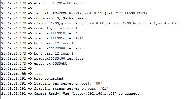
Serial.println("");
Serial.println("WiFi connected");
startCameraServer();
Serial.print("Camera Ready! Use 'http://");
Serial.print(WiFi.localIP());
local_IP = WiFi.localIP().toString();
Serial.println("' to connect");
Blynk.begin(auth, ssid, password, IPAddress(192,168,1,2), 8080);
}
void loop() {
// put your main code here, to run repeatedly:
Blynk.run();
if(digitalRead(PHOTO) == HIGH){
takePhoto();
}
}
Original link and full code here:
What should I change in order to make it work with my 3G router? I tried to replace like this
Blynk.begin(auth, ssid, password, IPAddress(192,168,1,2), 8080);
with
Blynk.begin(auth, ssid, pass, "myhostname", 9443);
Only the button worked (LED lights up) but no pictures are taken.
Please advise if I need to start a new topic on this.
Well, you have a…
and a…
You shouldn’t have both.
Pete.
The sketch is working as it is. If I remove WiFi.begin(ssid, password); the sketch doesn’t work.
For 3G if I replace as mentioned above I get only the button working which I assume means camera connects to the server. Serial monitor says camera is connected and appears in the 3G router connected devices list.
So, if you’re setting-up your own WiFi connection then you should be using Blynk.config and Blynk.connect…
Pete.
I’m sorry but this is beyond my limited knowledge and skills. I’m looking for something already working that I can replicate and that would need only slight adjustments.
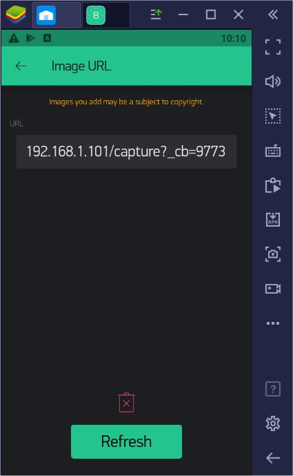
![]()
Port 80 is probably being blocked by your ISP, and if you want the images to be visible to the Blynk server/app then you need to provide a fully qualified URL that is visible to the server and the app/emulator device.
192.168.1.101 is LOCAL to your mobile router network, and isn’t resolvable outside of that network. You’d need to use a DDNS service to translate the public IP address of the router into a URL that you can use in the app .
Pete.
I’m already using a DDNS service that’s why I’m using this line:
Blynk.begin(auth, ssid, password, "myhostname", 9443);
I suppose the Blynk screenshot above shows that it sees the 192.168.1.101 IP.
You’re using a DDNS to allow you to resolve the public IP of your home network from your mobile router.
If the IP Cam is attached to your mobile router then you need a DDNS service (and updater of course) to allow you to resolve the public IP of your mobile router so that you can use this in your app’s connection string for the video streaming widget.
Pete.
My ESP32-CAM connects to my 3G router the same way as my NodeMCU. The 3 G router has a dynamic IP and I can’t install any updater on it so how is that supposed to work?
The updater doesn’t need to be configured within the router firmware, it can be running on any device connected to that network.
But, you can test the DDNS by manually updating the service with the current public IP address of your mobile router.
Here’s a DDNS updater sketch that will run on an ESP8266 or NodeMCU device…
Pete.
So should I just insert this somewhere in my cam code or else?