I did some search but couldn’t find much on this issue but if this was discussed before please point to appropriate link/s and or topic/s.
I have a NodeMCU project (sensor station) which I managed to get working setting up a Blynk local server (I also used a hack to get this station running using a SIM900 module discussed in another topic). I’m running Blynk on my PC using Bluestacks android emulator.
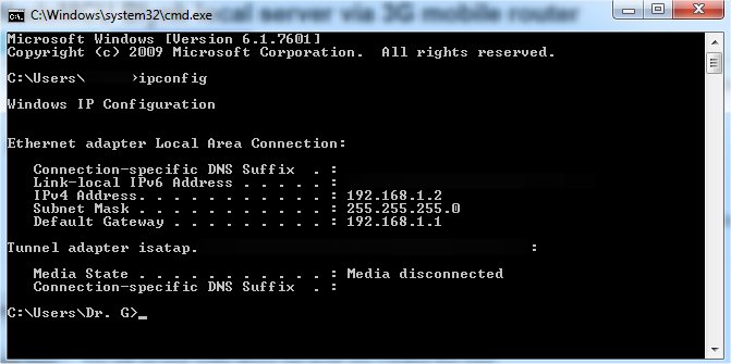
NodeMCU connects to the PC local Wi-Fi router using an 192.168.1.2 IP address. PC connection to internet is: optical cable -> optical decoder - > Wi-Fi router -> PC.
I’ll need this station at a remote location which will connect to a mobile 3G Wi-Fi router with SIM card and I’ll need it to connect directly to my PC in order to setup a local Blynk server.
I’ve set a No-Ip account and got a host name which I inserted into the code in place of the local IP address (using the same auth token) however I can’t connect to my PC.
Code changed from this:
Also changed ssid and pass for the 3G device but same auth token as for the WifFi server.
My questions are:
1/ do I need to use another email account in order to run the same project (and copy it) this time via 3G or I can sign off the local Wi-Fi already working one and only change the server IP with my PC’s public IP? In other words can I have the same project (with same auth token) from the same email account but only change connection type?
2/ I tried to add a new project while signed in the current Wi-Fi one but I don’t seem to be able to change server IP?
3/ do I need to disconnect my local Wi-Fi router from the whole picture (I can do that as it’s of little use for me)?
4/ what would be the procedure to get this 3G project going?
I’m running AVG Internet Security if that’s of any importance.
I’ve read through your hardware description several times, and have come to different understandings each time. But, there are so many grey areas in your description that it’s impossible to get to a point where I can answer your questions.
First of all, is your local server running on your PC, or some other device?
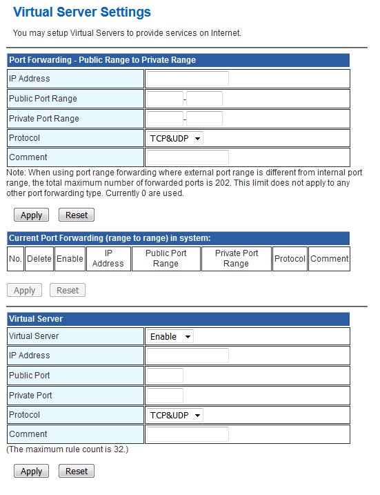
What port forwarding rules have you set-up in your router?
I’d suggest that you have another go at describing your hardware setup, maybe with some diagrams.
My connection to internet is: optical cable -> optical decoder - > Wi-Fi router -> PC.
My Blynk local server is set on my PC with local IP address 192.168.1.2
Blynk is running on my PC using Bluestacks android emulator.
NodeMCU connects to the Blynk server set on my PC using my WiFi router ssid and pass. No port forwarding was done on the router.
Now I need my NodeMCU to connect to internet via separate 3G mobile WiFi router with SIM card (with different than local ssid and pass) and then to my (same) PC where my Blynk local server is set. So I need to establish WiFi -> 3G (Alcatel One Touch Y580D) -> internet -> PC connection.
NodeMCU (shown as ESP-01E541) IP address at 3G router is 192.168.1.100.
If it’s a problem I can remove the local WiFi router from the connection described above.
With your current setup, data sent from the NodeMCU to the server is routed via IP address and port.
With your desired setup, data sent from your NodeMCU to your public IP address (resolved by using a DDNS service) arrives at your router and your router doesn’t know what to do with it.
So, you need to set-up a port forwarding rule in your router, so that when a packet arrives from your NodeMCU on port 8080, your router knows to forward it on to your Blynk server.
You also need a similar rule for port 9443 if you want to access either your server control panel or use the app/emulator from outside of your network.
NodeMCU connects to my 3G modem but no luck connecting to the server so far. Tried both 8080 and 9443 ports with Blynk Custom server setting upon log in.
#define SW_VERSION "   SW Ver. 3.2" // SW version will appears at innitial LCD Display
#include "stationDefines.h"       // Project definitions
#include "stationCredentials.h"

/* ESP & Blynk */
#define BLYNK_PRINT Serial    // Comment this out to disable prints and save space
#include <ESP8266WiFi.h>
#include <BlynkSimpleEsp8266.h>
WidgetLED PUMPs(V0);  // Echo signal to Sensors Tab at Blynk App
WidgetLED PUMPa(V5); // Echo signal to Actuators Tab at Blynk App
WidgetLED LAMPs(V1);  // Echo signal to Sensors Tab at Blynk App
WidgetLED LAMPa(V6); // Echo signal to Actuators Tab at Blynk App

/* TIMER */
#include "SimpleTimer.h"
SimpleTimer timer;

/* OLED */
#include <ACROBOTIC_SSD1306.h> // library for OLED: SCL ==> D1; SDA ==> D2
#include <Wire.h>

/* DHT22*/
#include "DHT.h"
DHT dht(DHTPIN, DHTTYPE);

/* DS18B20 Temperature Sensor */
#include <OneWire.h>
#include <DallasTemperature.h>
OneWire oneWire(ONE_WIRE_BUS);
DallasTemperature DS18B20(&oneWire);

void setup()
{
  Serial.begin(115200);
  delay(10);
  Serial.println("ArduFarmBot 2");
  Serial.println(".... Starting Setup");
  Serial.println(" ");

  pinMode(PUMP_PIN, OUTPUT);
  pinMode(LAMP_PIN, OUTPUT);
  pinMode(PUMP_ON_BUTTON, INPUT_PULLUP);
  pinMode(LAMP_ON_BUTTON, INPUT_PULLUP);
  pinMode(SENSORS_READ_BUTTON, INPUT_PULLUP);
  pinMode(soilMoisterVcc, OUTPUT);

  Blynk.begin(auth, ssid, pass, "myhostname", 8080);
  oledStart();
  dht.begin();
  DS18B20.begin();

  PUMPs.off();
  LAMPs.off();
  PUMPa.off();
  LAMPa.off();
  digitalWrite(PUMP_PIN, LOW);
  digitalWrite(LAMP_PIN, LOW);
  digitalWrite (soilMoisterVcc, LOW);

  waitButtonPress (SHOW_SET_UP); // Wait for Sensor Button to be pressed
  oled.clearDisplay();
  startTimers();
}

void loop()
{
 timer.run(); // Initiates SimpleTimer
  Blynk.run();
}

/****************************************************************
* Read remote commands
****************************************************************/
BLYNK_WRITE(3) // Pump remote control
{
  int i=param.asInt();
  if (i==1)
  {
    pumpStatus = !pumpStatus;
    aplyCmd();
  }
}

BLYNK_WRITE(4) // Lamp remote control
{
  int i=param.asInt();
  if (i==1)
  {
    lampStatus = !lampStatus;
    aplyCmd();
  }
}

/****************************************************************
* Read local commands (Pump and Lamp buttons are normally "HIGH"):
****************************************************************/
void readLocalCmd()
{
  boolean digiValue = debounce(PUMP_ON_BUTTON);
  if (!digiValue)
  {
    pumpStatus = !pumpStatus;
    aplyCmd();
  }

  digiValue = debounce(LAMP_ON_BUTTON);
  if (!digiValue)
  {
    lampStatus = !lampStatus;
    aplyCmd();
  }

  digiValue = debounce(SENSORS_READ_BUTTON);
  if (!digiValue)
  {
    turnOffOLED = !turnOffOLED;
    if (!turnOffOLED)
    {
      oled.setTextXY(0,0); oled.putString("UPDATING SENSORS");
      getDhtData();
      getSoilMoisterData();
      getSoilTempData();
      oledStart();
      displayData();
    }else oled.clearDisplay();
  }
}

/***************************************************
* Receive Commands and act on actuators
****************************************************/
void aplyCmd()
{
  if (pumpStatus == 1)
  {
    Blynk.notify("ArduFarmBot2: Warning ==>> Pump ON");
    digitalWrite(PUMP_PIN, HIGH);
    if (!turnOffOLED) displayData();
    PUMPs.on();
    PUMPa.on();
  }
  else
      {
        digitalWrite(PUMP_PIN, LOW);
        if (!turnOffOLED) displayData();
        PUMPs.off();
        PUMPa.off();
      }

  if (lampStatus == 1)
  {
    Blynk.notify("ArduFarmBot2: Warning ==>> Lamp ON");
    digitalWrite(LAMP_PIN, HIGH);
    if (!turnOffOLED) displayData();
    LAMPs.on();
    LAMPa.on();
  }
  else
      {
        digitalWrite(LAMP_PIN, LOW);
        if (!turnOffOLED) displayData();
        LAMPs.off();
        LAMPa.off();
      }
}

/***************************************************
* Automatically Control the Plantation based on sensors reading
****************************************************/
void autoControlPlantation(void)
{
  if (soilMoister < DRY_SOIL)
  {
    turnPumpOn();
  }

  if (airTemp < COLD_TEMP)
  {
    turnLampOn();
  }
}

/***************************************************
* Turn Pump On for a certain amount of time
****************************************************/
void turnPumpOn()
{
  pumpStatus = 1;
  aplyCmd();
  delay (TIME_PUMP_ON*1000);
  pumpStatus = 0;
  aplyCmd();
}

/***************************************************
* Turn Lamp On for a certain amount of time
****************************************************/
void turnLampOn()
{
  lampStatus = 1;
  aplyCmd();
  delay (TIME_LAMP_ON*1000);
  lampStatus = 0;
  aplyCmd();
}

/***************************************************
 * Send data to Blynk
 **************************************************/
void sendUptime()
{
  Blynk.virtualWrite(10, airTemp); //virtual pin V10
  Blynk.virtualWrite(11, airHum); // virtual pin V11
  Blynk.virtualWrite(12, soilMoister); // virtual pin V12
  Blynk.virtualWrite(13, soilTemp); //virtual pin V13
}
By the way what type of connection should I chose for this 3G project - WiFi, GSM or ethernet?
Last several times I noticed that 3G modem shows NodeMCU connected but it doesn’t initialize. Usually when the nodeMCU program starts running the OLED display will light up. It works flawlessly with my local WiFi server version though.
This is the last log where Iswitched between the WiFi code version and the 3G one.
> 00:36:00.279 INFO - xxx@gmail.com hardware joined.
> 00:36:38.058 INFO - xxx@gmail.com@gmail.com hardware joined.
> 00:42:31.615 INFO - xxx@gmail.com@gmail.com Blynk-app (android-22720) joined.
> 00:42:33.598 INFO - xxx@gmail.com@gmail.com Blynk-app (android-22720) joined.
> 00:43:02.422 INFO - xxx@gmail.com@gmail.com Blynk-app (android-22720) joined.
> 00:47:42.486 INFO - xxx@gmail.com@gmail.com Blynk-app (android-22720) joined.
> 00:55:19.129 INFO - xxx@gmail.com@gmail.com hardware joined.
> 00:55:58.004 INFO - xxx@gmail.com@gmail.com hardware joined.
Okay, in that case it appears that your sketch is not executing.
I’m guessing that maybe some of the pins (I guess in your stationDefines.h file) are illegal pins (in the GPIO 6-11 range) or you have something pulling GPIO0 LOW, or GPIO2 or 15 HIGH.
The 3G sketch is absolutely the same local Blynk server sketch working perfectly on the local WiFi network except for:
1/ In this line:
Blynk.begin(auth, ssid, pass, IPAddress(192,168,1,2), 8080);
IPAddress(192,168,1,2) is replaced with my No-Ip “myhostname” like this:
2/ Local WiFi credentials and auth token are replaced with 3G modem WiFi credentials and new project auth token.
When logging in Blynk connection type is Custom, IP 192,168,1,2.
And what do you see in the serial monitor when you run the “local server” version sketch on the same device?
If what you’ve posted is accurate, then the issue isn’t actually the Blynk.begin line of code.
Before that, in your void setup, you initialise the serial port then print 3 lines of text to the serial monitor. If these aren’t printing then the code execution isn’t getting as far as the Blynk.begin line of code, so something is preventing the code from executing.