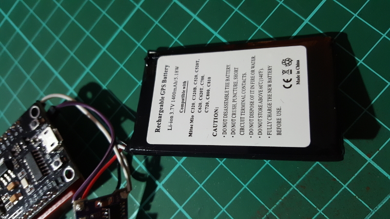
Hi, i drive my nodemcu with old gps battery (3.7v 1400 mAh) and i wanted to check my battery voltage via gauge.After some research i found a code and adapted to my sketch.Now it’s running like charm but it drains my battery so quickly.Can someone check my code what is wrong.I am not a coder that’s why i ask for your help guys.
#define BLYNK_PRINT Serial
#include <ESP8266WiFi.h>
#include <BlynkSimpleEsp8266.h>
#include <SimpleTimer.h>
#include <SPI.h>

char auth[] = "xxx";
char ssid[] = "xxx";
char pass[] = "xxx";
extern "C" {
  uint16 readvdd33(void);
}
SimpleTimer timer;

void myTimerEvent()
{
  Blynk.virtualWrite(V5, millis() / 1000);   // i really don't know what it is
  Blynk.virtualWrite(V10,readvdd33());  // i read value from that virtual pin
}

void setup()
{
  Serial.begin(9600);
  Blynk.begin(auth, ssid, pass);

   timer.setInterval(60000L, myTimerEvent); // i set that value for 60 sec interval
}

void loop()
{
  Blynk.run();
  timer.run();
}
As far as I can see, you are checking your battery every minute BUT, your NodeMCU is ALWAYS connected to the server and your battery goes down quickly.
Try to use Deep Sleep, this way, the NodeMCU maintains its RTC but shuts everything else off.
millis() is a function that provides the milliseconds since your sketch started, ergo this line sends your device uptime, in seconds, to widget V5 (normally a Value Display widget).
it would need to go in setup() after Blynk.begin() but I notice you don’t wait for a connection to Blynk in setup(). I would recommend:
void setup()
{
  Serial.begin(115200);   // 9600 only needed for inferior hardware
  Blynk.begin(auth, ssid, pass);
  unsigned long maxMillis=millis() + 8000;
  while ((Blynk.connect() == false) && ( millis() <= maxMillis)) {
  }
  Blynk.notify("NodeMCU Started!"); // ensure you have Notification widget in the project
  timer.setInterval(60000L, myTimerEvent); // i set that value for 60 sec interval
}
Thank you for helping copy&paste coders like me
I updated my sketch with few changes.For to check my board visually about it’s running or not i added breathing led option(thanks google). And i learned bit about how to do setup and loop options.I think now i can merge two basic codes like that
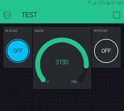
Are you getting these value from battery driven board or any other? I ask because i noticed that when i drive my board with battery value seems ok,when i connect my board to my computer i get lower values like 2.7.
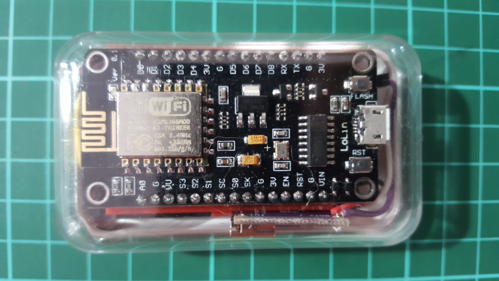
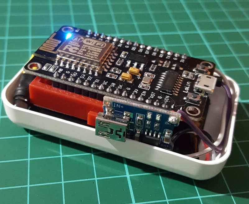
This is driven via a TP4056 Lipo charging board. The voltage from the module matches the battery exactly.
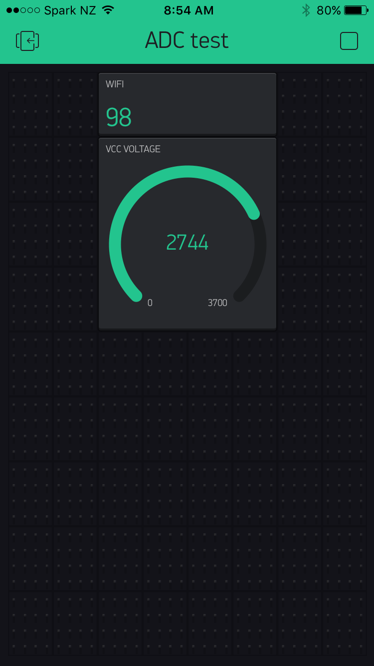
When I plug in the USB to charge the lipo via the TP4056, the output voltage climbs to 3.7v, but the reading says the same as 2.7v.
I read that its because on these dev boards the internal VCC voltage is read on the ESP chip after the VCC is used for other things on the boards like the CH340 chip… which causes the VCC to drop (because its all the ESP is getting)
Putting the battery directly in to the VIN/GND & 3V3/GND both give me 2.7v again.
As you see below i have same TP4056 charging board.I don’t know to much about what’s going on in the board electrically but maybe firmware version of board can cause this. Can you share your code also? My firmware is “v1.3.0.2 AT Firmware.bin”
Hope it helps.