So basically i'm doing a project where i connect the lights and fans of my house to arduino and connect a esp8266 module to it and control the lights and fans using blynk app.
But the other thing i wanted to do is using a bluetooth module and build a bluetooth remote using another arduino and a keypad so that whenever i press a button the keypad the signal is ssent via bluetooth to the arduino which controls the house lights.So i wanted to know if this is possible can i control the lights using both the blynk app and a blurtooth remote or is there a limitation.
And another thing is how to if the bluetooth way works whenever i press a button to turn on or off a light how to update the state in the app also?
So if the light is shown on in the blynk app and i press a butoon on my bluetooth controller to turn off the light the light state in the app should also change ow do i do that. I’m a complete beginner/noob and i do not under stand how virtual pins and blynk write virtual pin works if thats important.
The HC-05 module cannot be used by itself to connect to the blynk app. You will need to connect it to a wifi enabled microcontrolller such as the esp8266 module.
By the arduino controlling the house lights, are you referring to the esp8266 module?
I think it is a bit important for this project, so I will try to explain it to you.
A virtual pin is similar to a physical pin. It can be set high and low as required and can also be use to send analog values. The difference is that the virtual pin does not show the pin value by a GPIO pin on the microcontroller. The purpose of a virtual pin is to send data between the Microcontroller(in your case, an arduino and an esp8266) and the blynk app on your phone.
To do this, you can set the switch in the blynk app to a virtual pin(say, V3). Then you can set the esp8266 to read the state of the virtual pin and set the digital pin accordingly.
Example:
BLYNK_WRITE(V3)
/* This function is called whenever the Widget WRITES the data on the pin */
{
       int pinData = param.asInt(); //read the data Written to the pin as an int

      digitalWrite(relayPin, pinData); //set the pin connected to the relay hgh or low, depending upon the  value of the pinData
}
To do this you can use the function Blynk.virtualWrite function to set the value of the pin from the microcontroller connected to the bluetooth module. This will change the value of the virtual pin and thus cause a change in the blynk app and the other module connected to the lights.
I want to do a circuit where there are two modes of control first the usual blynk app control and the other i should also be able to control the lights using a bluetooth remote control so two modes of control
So if I’m in my house i use the bluetooth remote and if I’m out i use blank app
And as for the virtual pin part so if I set a button in blank app to be virtual pin can i use the same virtual pin button as a switch to turn on the light or does it only show the state of light
Do you have the Bluetooth remote working with the Arduino Uno to control the lighting relay, without any Blynk code running on the Uno?
If not, then this is the first thing you need to do. Once you have that working, post your Uno code and we’ll point you in the right direction to add-in the Blynk functionality.
At the moment, you appear to be using the hardware serial port on the Uno to communicate with the HC-05 and a SoftwareSerial port to communicate with the ESP-01. You’ll find it much easier to debug your code if you can see serial debug messages from the Uno, and you can’t do this properly if you are sharing the hardware serial port with another module (the HC-05 in this case).
You should either create another SoftwareSerial port and connect the HC-05 to this, or use a different MCU. This could be a Mega, with more serial ports, or a NodeMCU with built-in WiFi.
However, have you considered the fact that this system isn’t very expandable or sustainable?
Your Bluetooth remote could control many different lights, but you’d need to have a different receiver with Uno/Mega and HC-05 for each light (unless the lights are very close together and you add more relays, but lights in different locations would all need to be wired back to the same Uno/Mega).
Also, the battery life on the transmitter will be very short, as the Nano/HC-05 will be running 24/7.
Commercial remote controls use different circuitry to save battery life and that’s no do-able when you are using an Arduino to monitor the keypad for button presses.
Is this meant as a long-term home automation project, or as a project to demonstrate electronic/programming skills for a college course?
Yes without the wifi and blynk my bluetooth config works but i wanted to add more functionality to it.
how do i do that create another software serial port to communicate with my HC05.
and with a node MCU can i do this project cause i didn’t know node mcu could so this in the sense it could act like mini arduino.
for this im connecting all the relay modules near the mains of my house or at a place from where all the wiring for the appliances i want to connect are distributed from.
Battery Life? Like my transmitter will die or not work after some time?
or it just that my actual battery which powers the arduino and the transmitters will die or lose charge?
as for this i don’t know yet i’m just a beginner trying out but if this works i may install it in my house.
The same way that you created the one for the ESP-01.
That’s a bad approach. It’s very unlikely that each individual light will be wired back to your consumer unit. You’d be better having individual lights controlled by devices like Sonoffs or Shelly devices that contain a relay and ESP8266 device.
Yes, I’d expect the battery to last for around 1 day with this setup.
The NodeMCU is like an Arduino with a built-in WiFi chip, but it has more memory and more processing power than the Arduino - and it’s much cheaper and much smaller.
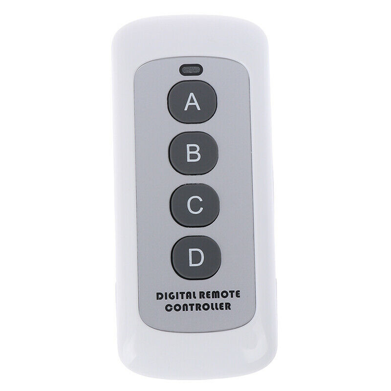
Personally, I think Bluetooth is a very poor technology to choose for this project. If you want to use a hand-held remote then 433MHz is a better choice in my opinion, as there are many off the shelf remotes available that solve the battery life issue. Items like this:
I use 433MHz and Sonoff/Shelly type devices, plus the Blynk app and Amazon Alexa to control the lights and other items in my house and my holiday home. This combination works very well for me…
I don’t quite understand what you’re saying “I’m a complete beginner”.
like ‘’‘SoftwareSerial espserial(ports my hc-05 is connected to)’‘’
So ill have to replace my aa or aaa battery for my bluetooth remote every day
is there any tutorial for rf integration and the parts requires are just rf reciever and a remote like the one u showed right? And instead of all this can i use IR remote i already have one but i didn’t plan on using it because it is dependent on point and click without pointing to the reciever it dosen’t work right? or will it? so i thought bluetooth was a better option
If you don’t understand the basics of domestic wiring then you have no business embarking on a project like this one. You’ll most likely kill yourself and other people within the house if you don’t have sufficient knowledge to implement this safely.