Hello Everyone in the Blynk comunnity, I am trying to control a light bulb with a relay, but there are times where i am also interested in just pressing a physical button instead of having to use my phone to turn on the light. I am using this code i found on the community by @castle and so far I am able to turn the light on and off through the blynk app but the physical button does nothing.
here is the code
#define BLYNK_PRINT Serial    // Comment this out to disable prints and save space
#include <ESP8266WiFi.h>
#include <BlynkSimpleEsp8266.h>
#include <SPI.h>
#include <TimeLib.h>
#include <SimpleTimer.h>

// You should get Auth Token in the Blynk App.
// Go to the Project Settings (nut icon).
char auth[] = "token";

// Your WiFi credentials.
// Set password to "" for open networks.
char ssid[] = "wifi name";
char pass[] = "password";

const int btnPin1 = 1;             // pin for your physical push btn switch or toggle switch. just for example
const int RelayPin1 = 3;         // pin for your relay outputs or any trigger output. etc.
//declaire your other pins here for your next buttons

SimpleTimer timer;              // add simple timer for the time interval scanning period of physical button input switch.
WidgetLED led1(V0);

void checkPhysicalButton();
int btnPin1State = LOW;           // ON
int RelayPin1State = HIGH;        // OFF

//*******Sets Relays to Off Position*****************
#define TURN_ON 0                 // TURN_ON and TURN_OFF are defined to account for Active High relays
#define TURN_OFF 1                // Used to switch relay states

void setup()
{
  Serial.begin (9600);
  Blynk.begin(auth, ssid, pass);
  {
    pinMode(RelayPin1, OUTPUT);            //  initialize your pin as output.
    pinMode(btnPin1, INPUT_PULLUP);        //  initialize your pin as input with enable internal pull-up resistor "input_pullup"
    digitalWrite(RelayPin1, RelayPin1State);
    digitalWrite(RelayPin1, TURN_OFF);     // remain off till command is receive

    // Setup a function to be called every 100 ms
    timer.setInterval(100L, checkPhysicalButton);
  }
  while (Blynk.connect() == false) {
    // Wait until connected
  }
}
void checkPin()
{
  // Invert state, since button is "Active LOW"
  if (digitalRead(btnPin1)) {
    led1.on();
  } else {
    led1.off();
  }
}
// Every time we connect to the cloud...
BLYNK_CONNECTED() {
  // Request the latest state from the server
  Blynk.syncVirtual(V1);
  // Alternatively, you could override server state using:
  //Blynk.virtualWrite(V1, RelayPin1State);
}
// When App button is pushed - switch the state
BLYNK_WRITE(V1) {                           // Map this Virtual Pin to your  Mobile Blynk apps widget.
  RelayPin1State = param.asInt();
  digitalWrite(RelayPin1, RelayPin1State);
  {
    //BLYNK_LOG("Got a value: %s", param.asStr());
    // You can also use:
    int i = param.asInt();
    int state;
    // Switch mode inverse//
    if (i == 0) {
      digitalWrite(RelayPin1, HIGH);
      Serial.println("Relay 1 = OFF");       // turn OFF your relay outputs
    }
    if (i == 1) {
      digitalWrite(RelayPin1, LOW);         // turn ON your relay outputs
      Serial.println("Relay 1 = ON");
      delay (300);                          // Delay response of your button switch (change it for you experimental but for me 300 is ok)
    }
  }
}

void checkPhysicalButton()
{
  if (digitalRead(btnPin1) == LOW) {
    // btnPin1State is used to avoid sequential toggles
    if (btnPin1State != LOW) {
      // Toggle LED state
      RelayPin1State = !RelayPin1State;
      digitalWrite(RelayPin1, RelayPin1State);
      // Update Button Widget
      Blynk.virtualWrite(V1, RelayPin1State);
    }
    btnPin1State = LOW;
  } else {
    btnPin1State = HIGH;
  }
}
void loop()
{
  Blynk.run();                               // Run Blynk
  timer.run();                               // Run SimpleTimer
}
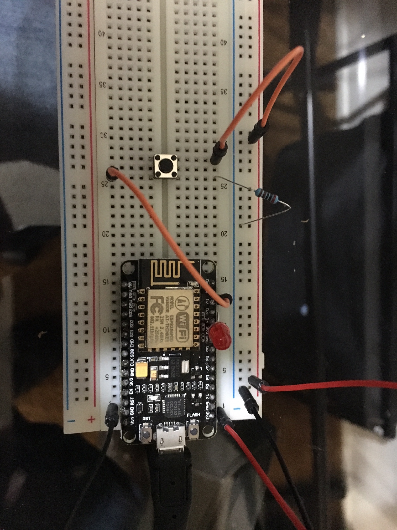
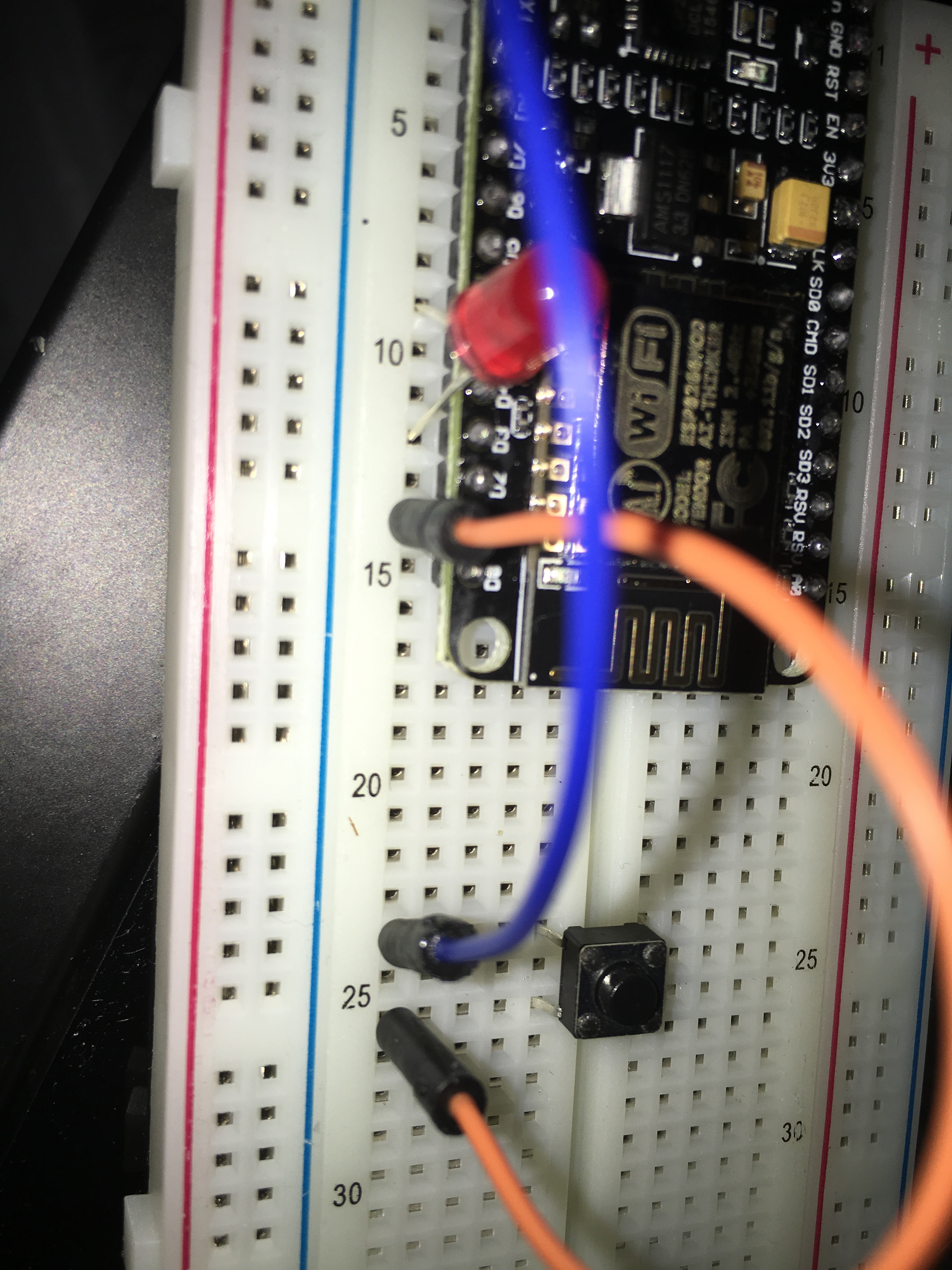
Here is a picture of my connections. (i am using an led to simulate the light)
I think there is a difference between a toggle button (physical) and a switch. Maybe that’s your issue? Not sure. I’m not really thinking straight at this moment.
I would recommend starting with an even simpler example then.
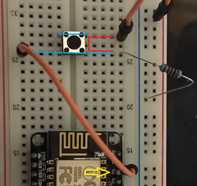
OK, what I see here, and this is based on zooming into your picture, so not necessarily correct, but it looks like your button is wired incorrectly.
First, as shown with the YELLOW arrow, your button appears to be plugged into D2, but the code is expecting it in D1
Second, if that button is the same as the type I have, it is always making connection across the BLUE lines, thus always grounding out D2
Third, when you do press the button, it is actually shorting out your power to ground, as shown in RED… but you are probably not noticing as it is thankfully through what appears to be a 1K resistor. It is also bringing D2 highish (splitting between the pin and the grounded resistor) - , but not the way you want it to.
hello!
i’m on phone right now, so it is a bit hard to analyze your code.
if all you need is to turn on/off a led from app and phisycal button, i think it is unnecesarry complicated.
but what i observed, that you are checking for the button state only every 100 milliseconds. that is probably not enough, it should be much more often, because youre probably missing the event. say every 10-20 millis. the other thing, that you are not using any debounce, so it is possible that the digital pin is actually turning on the led, but then instantly turning off.
reduce the 100L to 10, and try to implement some kind of debounce (at worst case add a 20milliseconds delay after reading the button)
when i will get to my pc i will try to help you with code.
good points, @Gunner, i didn’t observed this! however, the button may be different.
but anyway, there is no need for the “power” cable at the button if he is using input_pullup… nor the 1k resistor. only a cable to gnd.
Remove the power wire to the switch (on the right) and replace the resistor with same wire (but make sure it is on the ground, not the positive rail). Then rotate the button 45 degrees either direction to orient the pins properly so that pressing the button grounds out the D1 pin (brings it LOW as the code appears to desire).
If rotating the button makes it not fit properly, then just leave it where it is and wire ground and D1 so that they short out (according to the RED line I indicated earlier)… either side of the button is fine, just as long as both connections are on the same side.
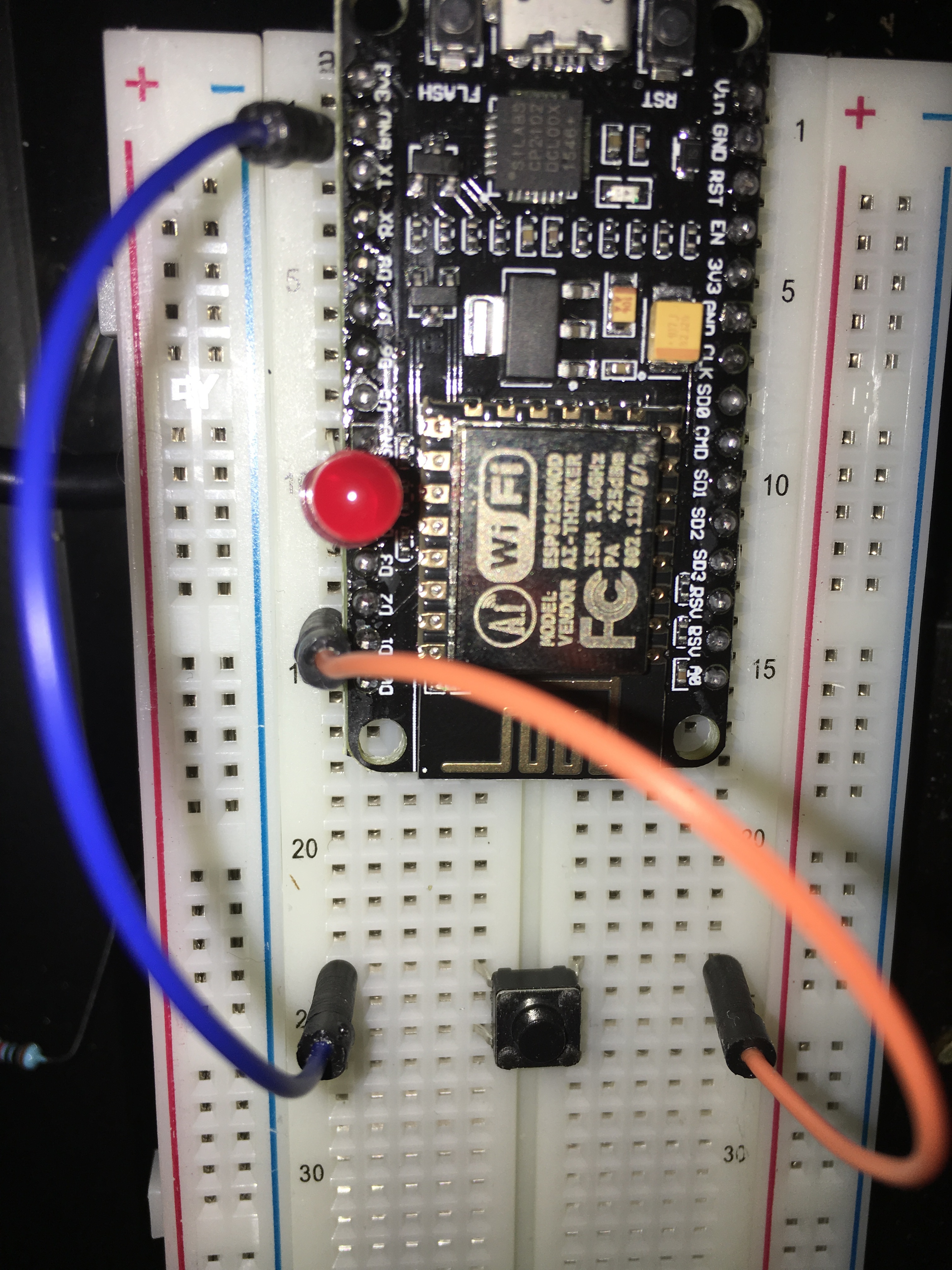
Re-submit a new picture if you are still having issues.
Move the orange wire to the same side of the button as the blue (although the way you have it should have the LED on all the time if the code is correct)… I honestly haven’t looked at the code side of it
And in concern to the code. Can you point out the areas that need to be fixed?
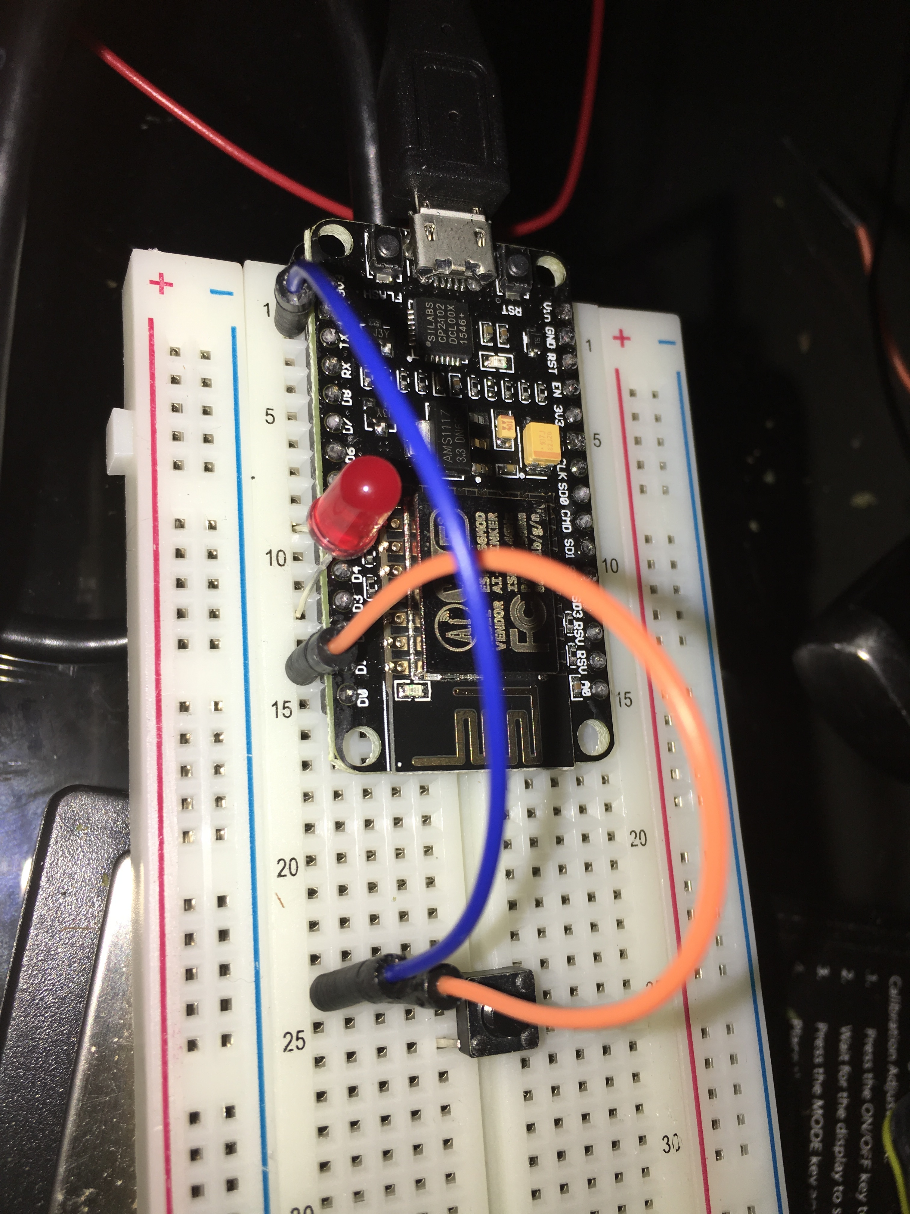
I also tried this code ( changed pins to D1 and D3 to match my connections) with no no luck regarding the physical button and same result regerding the app. Yes i tried a different button just in case
Well, the wiring seems ok now… Just to be sure, you could switch the BLUE wire to 3.3v… in case I am reading the code wrong and the button needs to be brought HIGH to work.
I will have to spend some time looking at the code (quickly reading and analysing code is not my forte).
And I do not have any ESP boards to test it on (in fact I just realised I needed to install new board support into my IDE just so I can compile ESP code… I live in the dark ages it seems ).
I will look into it when I can, but perhaps someone else will have chimed in by then.
@hgomez809 By the way… I just noticed that you have also asked for assistance with the same issue on two other threads… we (in the community) prefer if people didn’t do that (we call it spamming)… keep same issue too one thread at a time please.
another problem is that you apparently did not use any protective resistor on the led. so there are chances that you already fried the digital pin on the esp… and this is why not working. in your final project i understand you would like to use a relay. this will not work this way. you will need a mosfet or ss relay for the task.
afaik, these pins are not designed for supplying more than ~10-12mA. but if you are hooking up directly a led or relay like that, that can draw more. the digital pin should be protected with a 300 ohms resistor at least.
but sincerely and without offense, reading through these posts, i would highly recommend to you, to stop right now all these experiments, and take some time to learn about electronics and programming. even a simple task like this needs some basic knowledge.
do some electronics and arduino tutorials on youtube or arduino website, otherwise you can damage the components and just be frustrated about the lack of a feeling of success…
Good points! @wanek I was unaware that these ESP boards are so under powered on the pins… I commonly do tests with bare LEDs on my Arduinos at 5v (I know I shouldn’t but sometimes can’t find my pre-wired LEDS )
However, I was understanding that he had the Blynk widget button lighting up the LED just fine all this time? Perhaps not?
void checkPhysicalButton()
int btnPin1State = LOW; // ON
int RelayPin1State = HIGH; // OFF
You’re calling the function every 100ms but it’s not actually checking the state of the button attached to Pin 1, its writing LOW to Pin1 and HIGH to Pin3 each time it’s called.
Shouldn’t it be:
if (int btnPin1State = LOW)
{
int RelayPin1State = HIGH;
}
I also noticed that statement looked strange… It is not bracketed off with { }, and situated before the setup loop… but then for all I know that is particular of how ESP code variations work?? Seems to compile when I tried.


 ).
).