My point was that it’s missing an ‘if’ statement, so it doesn’t matter if the button is pressed or not, it always switches the relay to off every 100ms.
What the OP is actually doing is building the equivalent of a sonoff device. As you can buy these for a few Pounds/Dollars/Euros and flash the esp8266 with your own code, it doesn’t seem worth building your own.
Hi guys, @PeteKnight probobly something glitch from the functions, @hgomez809 just cross check again the original post. That code is working perfectly for arduino uno and atmega2560. @speed57 is using this code now since i share thesames sketch. I re view you modified sketch for esp pmce i have freel time. Im out of town by the way.
Upon actually looking at the code a bit closer, I realised that because those three lines are in the pre-setup position, it doesn’t matter about either the missing brackets or the “if” statement… it is just a one shot call of the void checkPhysicalButton() (assuming it even calls the function - it may do nothing where it is placed).
And the other two lines are setting up the variables for btnPin1State & RelayPin1State
Doh… I should have realised that earlier… too sleepy
As for why the button is not working… or even if anything else works or not… I think I will just watch and see what others say… it’s nap time for me
Well technically what he is doing is learning by trial and error… and I can’t fault that
void checkPhysicalButton()
int btnPin1State = LOW;// ON
int RelayPin1State = HIGH; // OFF
Is equivalent as
void checkPhysicalButton()
{
   int btnPin1State = LOW;// ON
}
int RelayPin1State = HIGH; // OFF
So relay RelayPin1State becomes a global variable, this is how the if statement works when omitting brackets, I wonder if the function declaration acts the same?
Okay, I finally decided drag out some hardware and look at it properly.
It’s now working for me with the code exactly as posted. The problem is with the way that the pins on the NodeMCU are referenced by the sketch.
Pin 4 (where the anode of the LED connects) isn’t Digital Pin 4, but the 4th pin up on the right hand side. Labelled RX on my board.
In the same way, the switch connects between Ground and the 3rd pin up on the right hand side - labelled TX, not Digital Pin 3 on the board.
Not easily I’m afraid, it was a very messy lash-up and it’s now all packed away again.
Here are the 4 pins on the bottom right hand side of the NodeMCU…
RX ------------> LED (+)
TX ------------> One side of Switch
Gnd ----------> LED(-) and the other side of the Switch
3.3V
This was with an LED that didn’t need a resistor.
I forgot to mention that the action of the physical and virtual switch are opposite to each other. Closing the physical switch switched the LED on and the virtual switch off. Switching the virtual switch on turns the LED off. Gunner already identified this issue with the code and you should be able to fix it easily enough by swapping one of the HIGH/LOW commands.
I want to thank everyone who has taken the time to help me. I know I don’t have coding knowledge nor electronics knowledge, but I do have a desire to learn. Once I get this project working flawlessly I will make a well-detailed tutorial on how to accomplish everything from start to finish. I know it will help others in my position.
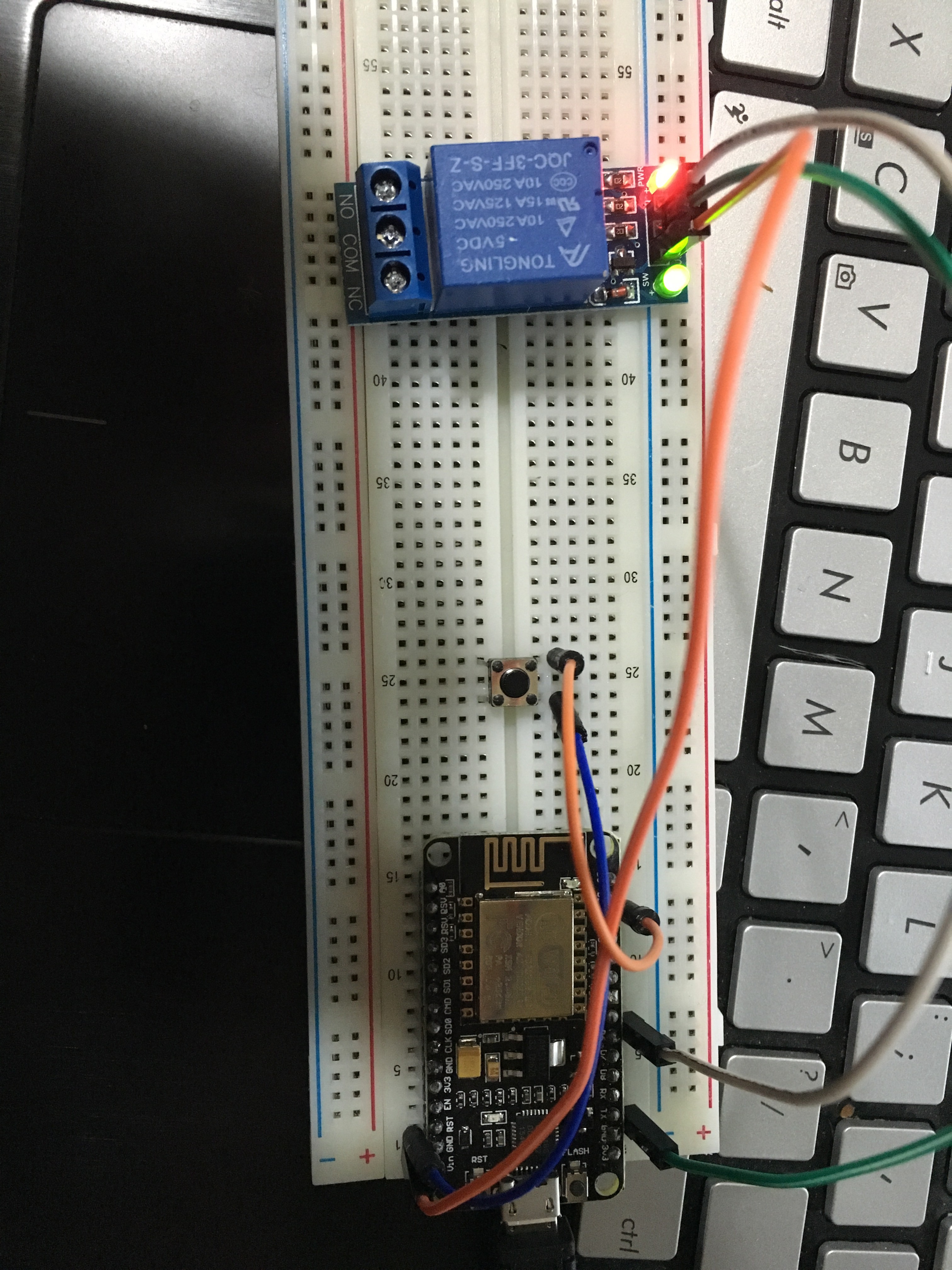
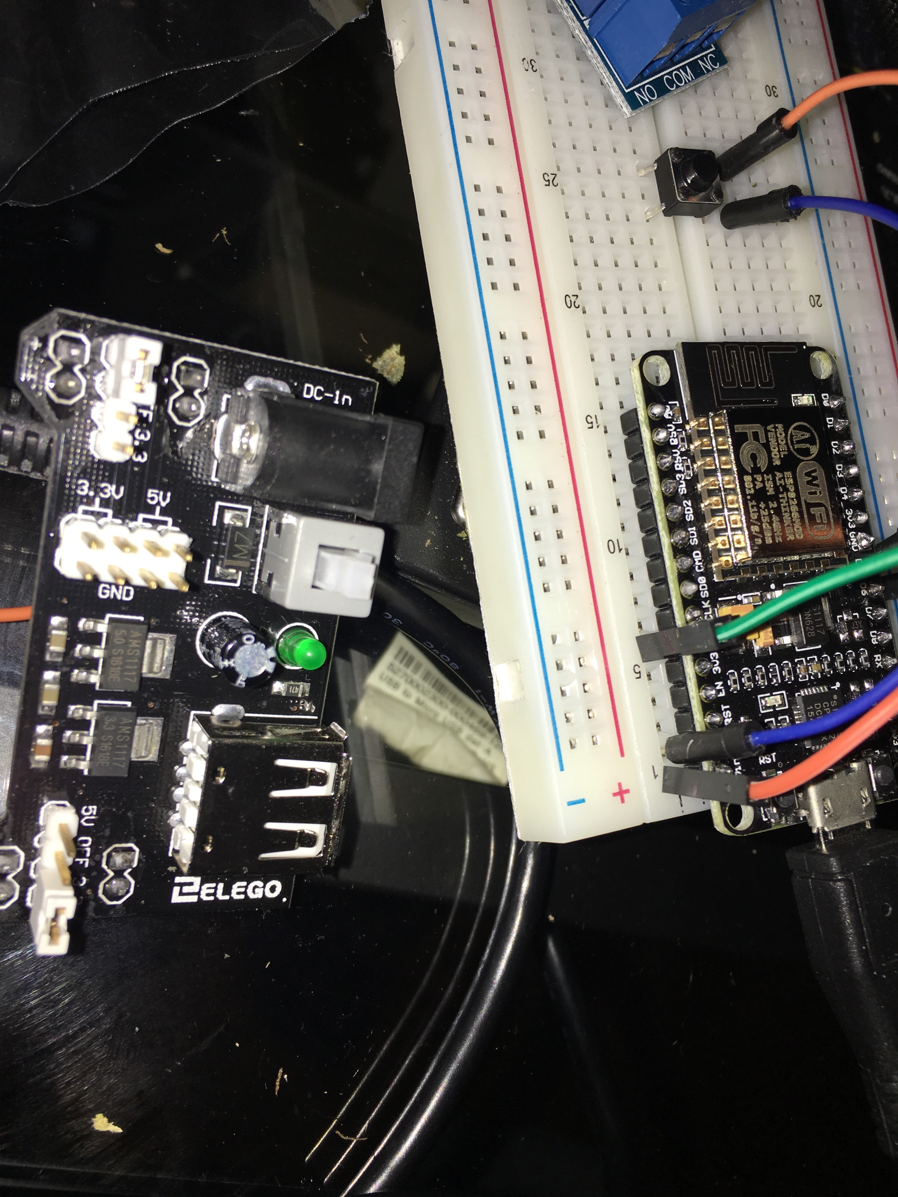
Okay back to business, @speed57 provided me a code made by @chrome1000 which is working pretty well. I only added the lines for wifi connection and changed the pin for the physical button. It can control the relay by using the physical button as well as the widget in the blynk app. I tried it with the led and worked flawless, but after hooking up an actual relay, it seems to be working but I don’t hear the (click) this relays normally make. I will leave a picture of the connections as well as the code, to see if anyone catches anything, any help is appreciated. I also did notice on the blynk app, when the light is off it shows as ON and when the light is on it shows as OFF.
It could be your relay is 5v and the ESP is 3.3. Possibly it’s not enough to switch the relay. Did you try and put 5v on the relay to see if it works? Also it could be an inverse relay, I’ve seen that happen too, where LOW is on and HIGH is off.
When you say it seems to be working, is that because the relay has a small LED that lights up when triggered?? If no LED or it is not lighting up, then the most likely issue is that it is not 3.3v compliant and thus not triggering properly.
If it does have an LED and it is lighting up, then make sure the relay coils are powered with 5v and not 3.3v.
And, well… since I know you have a camera Show us the relay board and how it is wired.
EDIT… I guess I type too slow… as I now see a picture
The board comes with one pin able to provide 5v. I am connecting it to the 5v pin. I uploaded a picture in the previous comment.
EDIT: sorry apparently there is a limit to the replies I can publish, So I have to edit this one for now.
@Gunner I just switched to a stronger charged, no luck, however I have a 2 channel relay working in my garage with the same board and that one triggers fine. I will try another relay just in case.
for this relay, while connected to the 5v the red and green led stay on, and when triggeting the on off switch, the green led dims a little and goes bright again when pressed again.
when connected to the 3.3v power source the green goes off and on according to the trigger. red stays on at all times.
Edit2: second relay, same results.
@Lichtsignaal is there any solution for that and keeping the same board?
Edit3: @Gunner should i connect it in a different way? to reverse it?
@Jamin I tried changing the pins but there is no difference.
Edit4:
Okay that much I understand. Any ideas as of why it is not clicking?
The red LED means the relay is triggered (coil energised)… but if still not clicking when toggling between triggered and off, then you may not be getting enough current over your USB power.
OK, that actually sounds right… The LED colours are just backwards from the relays I have.
RED is power (that should be the 5v VCC on the relay) and the green is showing the trigger (which is 3.3v) and triggered by the board.
It also sounds like your relay may be ON by default and OFF when triggered, which will draw more current at off times… I hate relays that work that way
If you are referring to the relay being ON by default… no, that is the way it is… you just change your code so that the pin is HIGH when OFF and LOW when ON.
Or, since the relay has a STDP (single throw double pole switch), just wire the outputs accordingly as the center is common and one side is normally closed and the other normally open… but I guess you might already know that as you have your garage setup in operation.
Low current is the most likely reason… try wiring up the relay VCC to a separate 5v (or 6v - OK for short term testing) battery source (just join the ground of the battery and the board together)