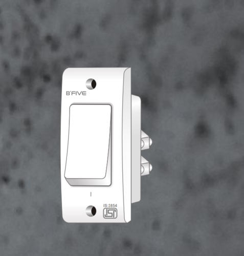
I am making a Home Automation project with blynk and manual switching with feedback. I want to use a 1-way switch instead of push switch to make this work. This is the switch.
My code is working with push switch but I want to use this 1-way switch. My code is here:
#define BLYNK_PRINT Serial
#include <ESP8266WiFi.h>
#include <BlynkSimpleEsp8266.h>
#include <ESP8266mDNS.h>  // For OTA with ESP8266
#include <WiFiUdp.h>  // For OTA
#include <ArduinoOTA.h>  // For OTA

BlynkTimer timer;

void checkPhysicalButton();

int relay1State = LOW;
int pushButton1State = HIGH;

int relay2State = LOW;
int pushButton2State = HIGH;

int relay3State = LOW;
int pushButton3State = HIGH;

int relay4State = LOW;
int pushButton4State = HIGH;

#define AUTH "AuthToken"  // You should get Auth Token in the Blynk App.
#define WIFI_SSID "SSID"                   //Enter Wifi Name
#define WIFI_PASS "Pass"                   //Enter wifi Password

#define SERVER "blynk-cloud.com "             // Comment-out if use Blynk hosted cloud service
#define PORT 8442

#define RELAY_PIN_1      12   //D6
#define RELAY_PIN_2      16   //D0
#define RELAY_PIN_3       4   //D2
#define RELAY_PIN_4       5   //D1

#define PUSH_BUTTON_1     2   //D4
#define PUSH_BUTTON_2    14   //D5
#define PUSH_BUTTON_3    13   //D7
#define PUSH_BUTTON_4     1   //TX

#define VPIN_BUTTON_1    V12
#define VPIN_BUTTON_2    V13
#define VPIN_BUTTON_3    V14
#define VPIN_BUTTON_4    V15

#define OTA_HOSTNAME "Home_Automation"


BLYNK_CONNECTED() {

  // Request the latest state from the server

  Blynk.syncVirtual(VPIN_BUTTON_1);
  Blynk.syncVirtual(VPIN_BUTTON_2);
   Blynk.syncVirtual(VPIN_BUTTON_3);
  Blynk.syncVirtual(VPIN_BUTTON_4);

  // Alternatively, you could override server state using:
 // Blynk.virtualWrite(VPIN_BUTTON_1, relay1State);
 // Blynk.virtualWrite(VPIN_BUTTON_2, relay2State);
 // Blynk.virtualWrite(VPIN_BUTTON_3, relay3State);
 // Blynk.virtualWrite(VPIN_BUTTON_4, relay4State);

}

// When App button is pushed - switch the state

BLYNK_WRITE(VPIN_BUTTON_1) {
  relay1State = param.asInt();
  digitalWrite(RELAY_PIN_1, relay1State);
}

BLYNK_WRITE(VPIN_BUTTON_2) {
  relay2State = param.asInt();
  digitalWrite(RELAY_PIN_2, relay2State);
}
BLYNK_WRITE(VPIN_BUTTON_3) {
  relay3State = param.asInt();
  digitalWrite(RELAY_PIN_3, relay3State);
}
BLYNK_WRITE(VPIN_BUTTON_4) {
  relay4State = param.asInt();
  digitalWrite(RELAY_PIN_4, relay4State);
}

void checkPhysicalButton()
{
  if (digitalRead(PUSH_BUTTON_1) == LOW) {
    // pushButton1State is used to avoid sequential toggles
    if (pushButton1State != LOW) {

      // Toggle Relay state
      relay1State = !relay1State;
      digitalWrite(RELAY_PIN_1, relay1State);

      // Update Button Widget
      Blynk.virtualWrite(VPIN_BUTTON_1, relay1State);
    }
    pushButton1State = LOW;
  } else {
    pushButton1State = HIGH;
  }

  if (digitalRead(PUSH_BUTTON_2) == LOW) {
    // pushButton2State is used to avoid sequential toggles
    if (pushButton2State != LOW) {

      // Toggle Relay state
      relay2State = !relay2State;
      digitalWrite(RELAY_PIN_2, relay2State);

      // Update Button Widget
      Blynk.virtualWrite(VPIN_BUTTON_2, relay2State);
    }
    pushButton2State = LOW;
  } else {
    pushButton2State = HIGH;
  }

  if (digitalRead(PUSH_BUTTON_3) == LOW) {
    // pushButton3State is used to avoid sequential toggles
    if (pushButton3State != LOW) {

      // Toggle Relay state
      relay3State = !relay3State;
      digitalWrite(RELAY_PIN_3, relay3State);

      // Update Button Widget
      Blynk.virtualWrite(VPIN_BUTTON_3, relay3State);
    }
    pushButton3State = LOW;
  } else {
    pushButton3State = HIGH;
  }

  if (digitalRead(PUSH_BUTTON_4) == LOW) {
    // pushButton4State is used to avoid sequential toggles
    if (pushButton4State != LOW) {

      // Toggle Relay state
      relay4State = !relay4State;
      digitalWrite(RELAY_PIN_4, relay4State);

      // Update Button Widget
      Blynk.virtualWrite(VPIN_BUTTON_4, relay4State);
    }
    pushButton4State = LOW;
  } else {
    pushButton4State = HIGH;
  }
}

void setup()
{

  Serial.begin(115200);
  Blynk.begin(AUTH, WIFI_SSID, WIFI_PASS,"blynk-cloud.com", 8442);
  ArduinoOTA.setHostname(OTA_HOSTNAME);  // For OTA - Use your own device identifying name
  ArduinoOTA.begin();  // For OTA

  pinMode(RELAY_PIN_1, OUTPUT);
  pinMode(PUSH_BUTTON_1, INPUT_PULLUP);
  digitalWrite(RELAY_PIN_1, relay1State);


  pinMode(RELAY_PIN_2, OUTPUT);
  pinMode(PUSH_BUTTON_2, INPUT_PULLUP);
  digitalWrite(RELAY_PIN_2, relay2State);


  pinMode(RELAY_PIN_3, OUTPUT);
  pinMode(PUSH_BUTTON_3, INPUT_PULLUP);
  digitalWrite(RELAY_PIN_3, relay3State);


  pinMode(RELAY_PIN_4, OUTPUT);
  pinMode(PUSH_BUTTON_4, INPUT_PULLUP);
  digitalWrite(RELAY_PIN_4, relay4State);

  // Setup a function to be called every 100 ms
  timer.setInterval(500L, checkPhysicalButton);
}

void loop()
{
  Blynk.run();
  ArduinoOTA.handle();  // For OTA
  timer.run();
}
Do you mean the simple switch to turn ON/OFF lights in our houses? Ok to using Blynk as switch state feedback, but I don’t understand how you could control relays both from the app and from the physical 1-way switch. Am I missing something?
If you want to use a 1-way switch, you will not have an ON and an OFF state but a change of state at each exchange of the switch position.
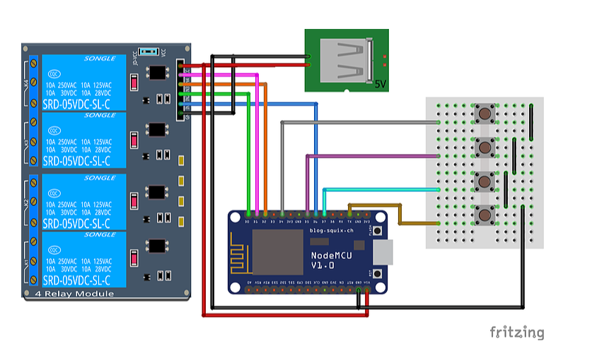
Check out the code. I am using push switches to high the relay as well as the Blynk app to switch on/off. But it’s working only with push switch but I want to add the 1 way switch in this project. Check out this diagram for more reference:
Let’s take an example. You press the switch and relay 1 goes HIGH. Then turn off the relay via the application. If you press the switch to the new position, what do you want to happen?
I think YOU will need to come up with some clever coding to handle these types of scenarios. Have you even tried? Or are you hoping someone will just write the code for you?
Yeah I’m trying my level best but I’m a beginner and I can’t find any solution for this. That’s why I am asking for help if you have any suggestion then you can give or else thank you for just over-viewing my project.
what i can understand is he is trying to turn on the appliance from the normal switch and later we turn it on off via the app it should not matter, when we toggle the switch it should turn on of off knowing the previous state. Like the SONOFF do. They get connected to the normal switches, Obviously the switch state(position) will confuse whether it is on or off as it will not change its position by itself when we use the app to turn on or off.
lets say GPIO will get connected to GND(from switch) and it will trigger the appliance. later turn off the device from app.
Now when the switch is again pressed the GPIO will float and now the appliance must turn back on,
This is what i can understand by his explanation…
But doing so may put few pins floating and few connected to GND… This may affect the ESP while booting during a power failure.
Just to elaborate on what I said before about using interrupts, here’s a more in-depth explanation about what I think the possible solutions are (hopefully I’m understanding the question correctly.
The current code scans the pushbutton every 500ms (quite a long delay)
timer.setInterval(500L, checkPhysicalButton);
and then has some debounce code, which is probably redundant with 500ms scans of the button state:
  if (digitalRead(PUSH_BUTTON_3) == LOW) {
    // pushButton3State is used to avoid sequential toggles
    if (pushButton3State != LOW) {

      // Toggle Relay state
      relay3State = !relay3State;
      digitalWrite(RELAY_PIN_3, relay3State);

      // Update Button Widget
      Blynk.virtualWrite(VPIN_BUTTON_3, relay3State);
    }
    pushButton3State = LOW;
  } else {
    pushButton3State = HIGH;
  }
This same approach could be used with a toggle switch rather than a pushbutton, but would require a flag to store the previous state of the switch and a check to see when that state has changed. If the current state is not equal to the previous state the the switch has been flipped and the various processes such as toggling the relay and updating the corresponding button in the Blynk app need to be called.
The other way is to attach an interrupt to the pin that the toggle switch is connected to, and set it as a CHANGE type. Whenever the switch changes state (the pin switches from HIGH to LOW or LOW to HIGH then the interrupt will be triggered.
This definitely does need some debounce code and this code needs to incorporate a timer to ensure that a certain period of time has elapsed between interrupts (100ms maybe?). When you declare the interrupt you need to specify which function will be called when the interrupt is triggered. This is the function that will contain the debounce code, and which will call the processes that toggle the relay and update the button widget in Blynk.
There are some rules about using interrupts that aren’t documented very well (or at all in some cases) in the standard Arduino code documentation:
Variables that change within the function that is called when the interrupt is triggered (known as the Interrupt Service Routine or ISR) must be declared as volatile
The name of the ISR must include the ICACHE_RAM_ATTR attribute, like this: void ICACHE_RAM_ATTR your_function_name()
The ISR function must be before the void setup() or you must pre-declare the ISR function name at the top of your code like this void ICACHE_RAM_ATTR your_function_name(); This is known as a Forward Declaration.
Your ISR code must be ‘lean and mean’, doing just the bare minimum and avoiding thinks like serial prints wherever possible.
Whichever approach is used, the pinmode declaration for the pin that has the switch attached to it should include a PULLIP parameter, so the pin doesn’t float at a voltage that is neither HIGH or LOW.
Obviously we will have the input pullup in the pinmode… What i meant was say we have 4 switches there are plenty of permutation like (during the boot) all pins may be low, all pins may be left floating(input pullup), or any one or two or three may be connected to GND… I feel these may stop the device from booting properly. If we are using GPIO0 then its definitely going into programming more, so we should not use it.
why do you evaluate the switch status only if it is low?
what is the functionality of State1(2,3,4) that you use in the code?
I try to answer the 2 questions:
with 1-way switches you cannot evaluate a single state of the switch but you must evaluate the change of state;
the code you posted cannot work. You have to remove the old code you used with push buttons. In my example code I used the State variable that “contained” the state of the switch input to check the change of state.
void checkPhysicalButton()
{
    int State = digitalRead(PUSH_BUTTON_1); //"State" containes the logical level of the switch
    if (State != oldState) { //Change of the input state? Yes if I change the switch position
        oldState = State; //in order to be ready for a new change of state
        relay1State = !relay1State;
        digitalWrite(RELAY_PIN_1, relay1State);
        Blynk.virtualWrite(VPIN_BUTTON_1, relay1State);
    }
    ... and so on...
So, in my opinion, you don’t need pushButton1State.
P.S.: as @PeteKnight said, a 500ms check interval is quite long. Reduce it.
If you don’t like this procedure, you can try to implement the @PeteKnight solution: CHANGE Interrupt: it’s smarter, but probably a little more complex.
I agree with @daveblynk. I think that debounce functions are more useful for push buttons as they are mechanically more subject to this problem. About 100 ms is a correct time interval.
Can you show us what are you upto with the code ? It can be helpful for others or we can improve it if needed…
EDIT
After seeing this post i took 4 toggle switches(Normal wall switches) and connected one terminal to GND and other to VCC via a 10k resistor. And connected the point between VCC and 10k resistor to the input pin of the nodemcu.
Uploaded the sketch it works fine. later when i restart the nodemcu it wont boot, as few pins will be high and few will be low. While experimenting i burnt up my (ESP12F on a breakout board). Now i after reboot it will go into programming mode. GPIO0 is shorted i guess. So it works fine only after uploading the code, after reboot it will ask to upload a new program.
input pins D1 D4 D6 D7. output D2 D0 D5 D8. (WORKS FINE WITH PUSH BUTTON)