Hi Blynkers
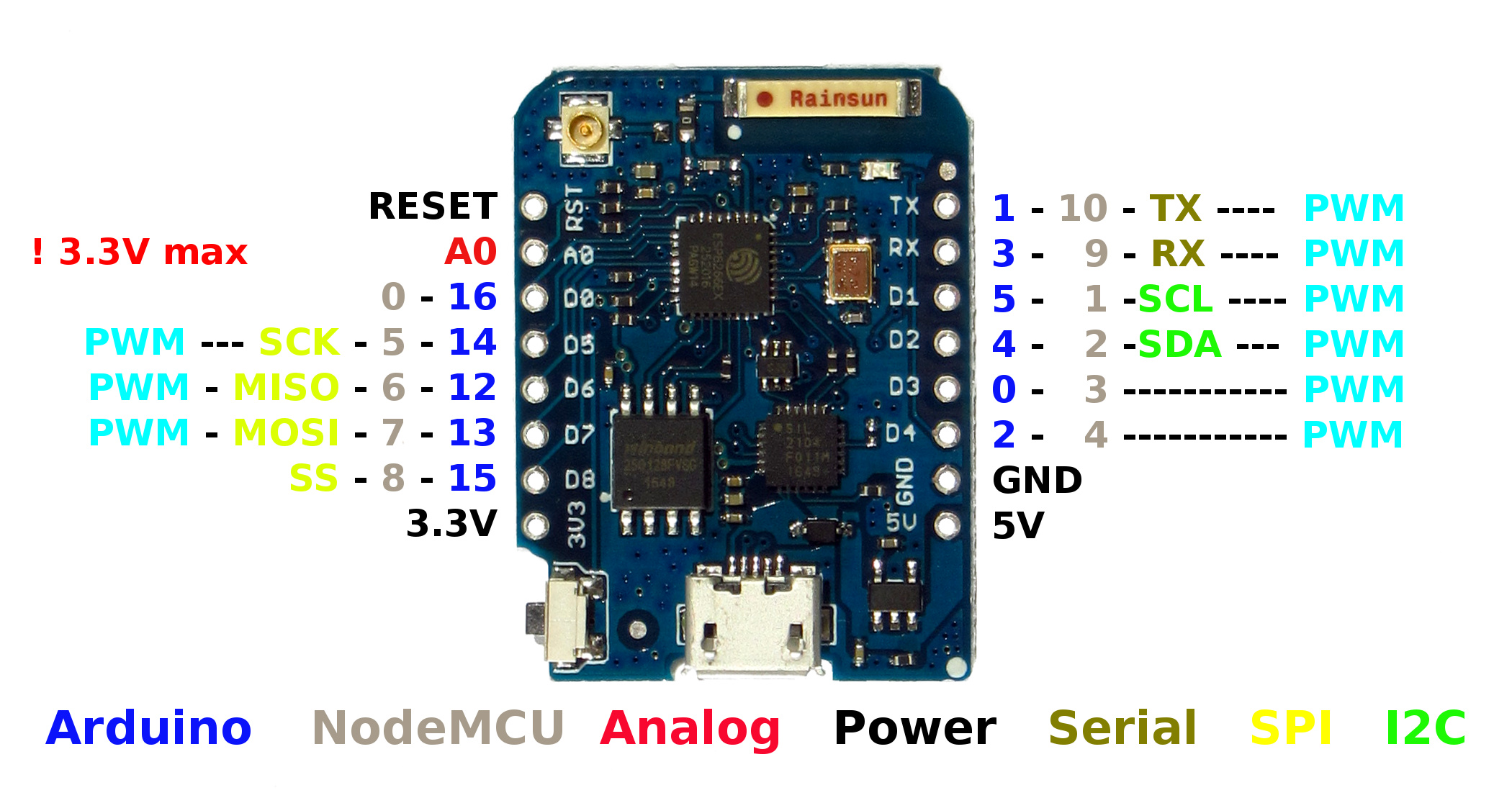
I need some help to realize my current project. In fact it´s pretty simple. There is a lamp (230V) and a switch. When it´s on, a relay switches and I get a signal on D1 from my Wemos D1 mini, so usually I know it´s current status.
This status should be shown in Blynk app. With an other relais, which get controlled over the Blynk App I want realize a second switch position.
Now I want know how to synchronize the current switch status with Blynk. Later I also want make a third switch position using a IR-receiver which is also connected on the Wemos. Until now I am able to get the different values from the IR-transmitter when I press the keys.
I would like to know how I synchronize an incomming signal on e.g. D1 with Blynk, so that I can handle with Blynk. For example: I get an HIGH Signal on D1, that in Blynk APP should turn on a Widget LED and a physical LED. If I press a button in Blynk App I want be able to switch off again the LEDs. The Widget LED which is only the status LED should again change his status.ö
Finally I would rearch a toogle. If you look at the wiring above (and you can understand it ) you see that I should be able to switch the lamp from two switch positions. One switch is a normal toggle switch and the second “switch” is in fact a toggle relay which get controlled by the Wemos D1 mini (Blynk).
if (digitalRead(D1) == HIGH) {  // PS best to use Arduino pin numbering and NOT the silk screened label as it will work across all ESP8266 boards.
Blynk.virtualWrite(vPin, 1);  // Set the vPin to the one on your widget you want to control
} else {
Blynk.virtualWrite(vPin, 0);  // Set the vPin to the one on your widget you want to control
}
Or even simpler…
Blynk.virtualWrite(vPin, digitalRead(5)); // Read Digital pin and send same state to Widget with corresponding vPin
Use Virtual Pins and control all your GPIO via Blynk functions to make the App and Physical synchronization easier.
// using interrupts or timer polling to scan for externally activated switch/sensor
Blynk.virtualWrite(vPin, digitalRead(5));  // Read Digital pin and send same state to Widget with corresponding vPin
Blynk.syncVirtual(vPin)  // follow up by acting as if you pressed the Button Widget to process the corresponding Blynk Function
BLYNK_WRITE(V0) {  // Runs whenever the corresponding widget changes state
  int value = param.asInt(); // Get value as integer
  if (value == 1) {
  // do whatever to turn on your thing
  } else {
  // Do whatever to turn off your thing
  }
}
I am still trying to find a simple method to toogle
The output depend from input. If for example I get on input a LOW-Signal I want be able to output a HIGH Signal on OUTPUT, if input signal is HIGH, the output pin should output a LOW signal. Naturally the output should not change his change automatically. Only if I push/switch a push/button in Blynk-App or I get a IR-signal from my IR-transmitter. By getting the value 0xFF30CF output sould change state to HIGH and by the value 0xFF18E7 should change state to LOW. (The App-Button only toggles while the IR-transmitter send HIGH or LOW by pressing two different pushes).
To get the values from IR-transmitter isn´t any problem, also reading the current state on input works.
I only needed help to set the ouput-states.

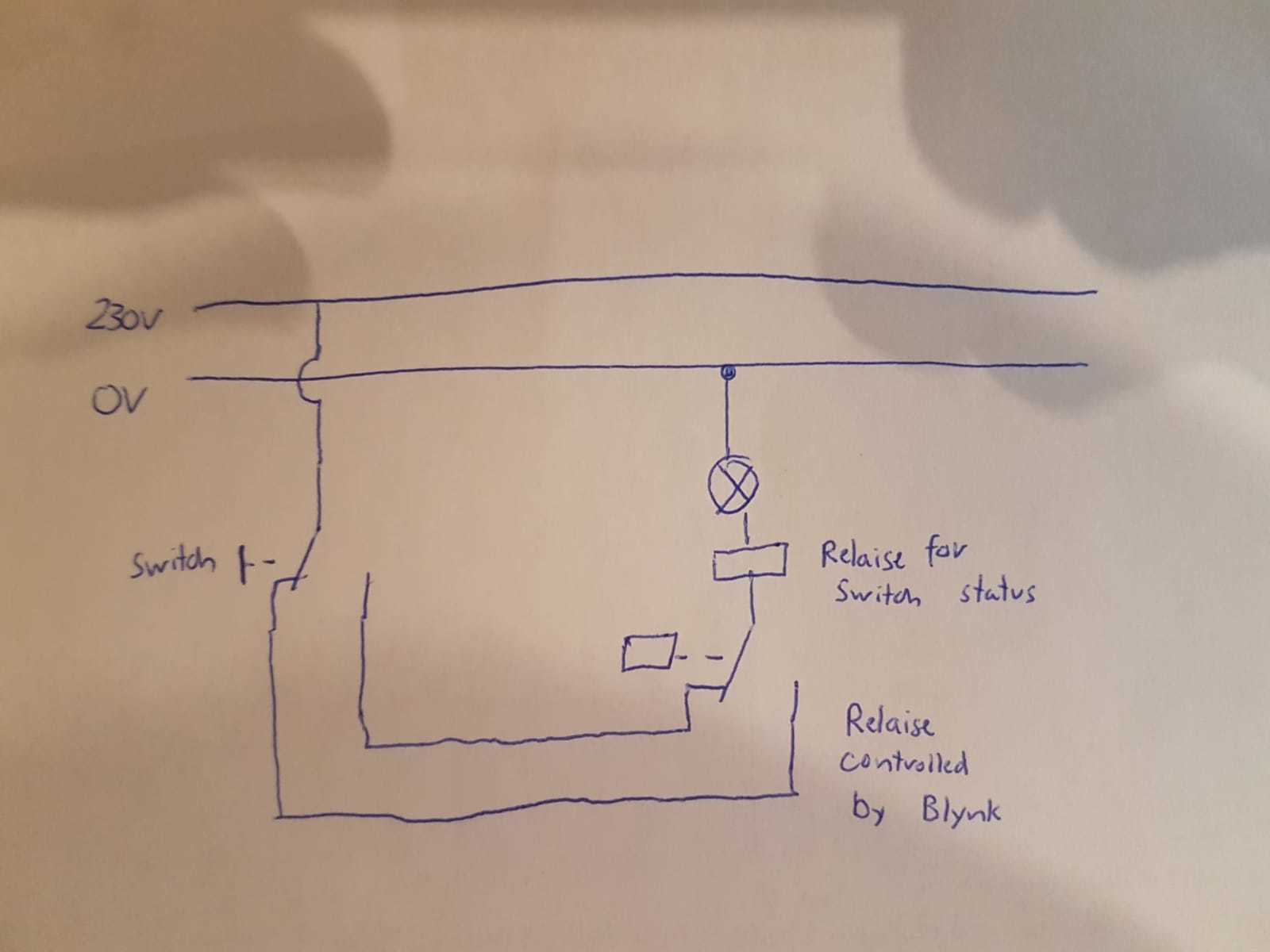

 ) you see that I should be able to switch the lamp from two switch positions. One switch is a normal toggle switch and the second “switch” is in fact a toggle relay which get controlled by the Wemos D1 mini (Blynk).