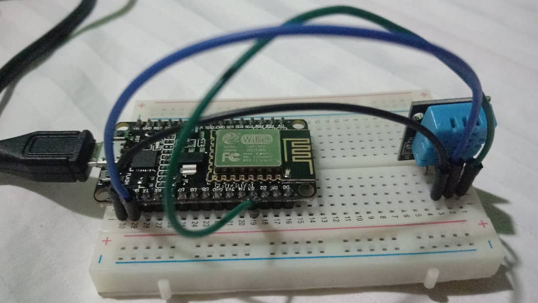
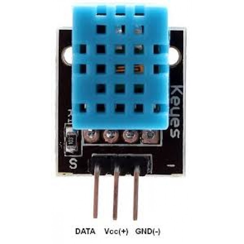
Hello, I’m getting this failed to read from DHT sensor. I already checked the pin as D3 is V0 and I also tried D4 which is V2. I’m using NodeMCU. I already refer the similar problem but most of them are the wiring problems. I also already referred to the Dht datasheet to make sure im pining the correct pin (GND> - and 3.3V > Vcc also D3> S)
#include <ESP8266WiFi.h>
#include <BlynkSimpleEsp8266.h>
#include <DHT.h>

char auth[] = "URHaTHZ_E1ufJj4Qc_vT4K8aumNlXCdF"; //Enter the Auth code which was send by Blink
char ssid[] = "Bilik Gerakan";  //Enter your WIFI Name
char pass[] = "smkbg@123";  //Enter your WIFI Password

#define DHTPIN 0          // D3

// Uncomment whatever type you're using!
#define DHTTYPE DHT11     // DHT 11
//#define DHTTYPE DHT22   // DHT 22, AM2302, AM2321
//#define DHTTYPE DHT21   // DHT 21, AM2301

DHT dht(DHTPIN, DHTTYPE);
BlynkTimer timer;

// This function sends Arduino's up time every second to Virtual Pin (5).
// In the app, Widget's reading frequency should be set to PUSH. This means
// that you define how often to send data to Blynk App.
void sendSensor()
{
  float h = dht.readHumidity();
  float t = dht.readTemperature(); // or dht.readTemperature(true) for Fahrenheit

  if (isnan(h) || isnan(t)) {
    Serial.println("Failed to read from DHT sensor!");
    return;
  }
  // You can send any value at any time.
  // Please don't send more that 10 values per second.
  Blynk.virtualWrite(V5, t);
  Blynk.virtualWrite(V6, h);
}

void setup()
{
  // Debug console
  Serial.begin(9600);

  Blynk.begin(auth, ssid, pass);
  // You can also specify server:
  //Blynk.begin(auth, ssid, pass, "blynk-cloud.com", 8442);
  //Blynk.begin(auth, ssid, pass, IPAddress(192,168,1,100), 8442);

  dht.begin();

  // Setup a function to be called every second
  timer.setInterval(1000L, sendSensor);
}

void loop()
{
  Blynk.run();
  timer.run();
}