which Sensors are good for a energy metter?
Depends if you have a fixed or variable voltage and if it’s AC / DC.
Also maximum current comes into play when choosing the sensor.
For AC in general you can use toroidal transformers with different numbers of turns so the output (a current) is proportional to the current you want to measure.
To measure energy power consumption you need to measure AC voltage and AC current (if you are working with AC). To measure AC voltage you can you a voltage transformer to reduce 110v/220v to 9 or 5v and then a resistor divider so you can measure with a microcontroller (for example Arduino).
To measure AC current you can use a current transformer. A current transformer has AC current in the input and AC current in the output. It depends on the number of turns of the transfomer. If you look in google for current transformer you can understand how it works.
thanks for the reply. but i still not understand:
regarding the voltage part: if you use a transformer to reduce voltage say to 5 volts, than you still have ac 5v, not dc.
to use an mcu to measure voltage, that implies to have common gnd between the arduino and transformer (or voltage divider). but, because of the alternating current, you will have sometimes +5v compared to gnd, and sometimes -5v compared to gnd. the arduino will be destroyed if receives negative voltage on the pin…
or i’m completely missing something?
than there are other components in the circuit, not just a plain transformer + voltage divider?
Take a look at the ZMPT101B.
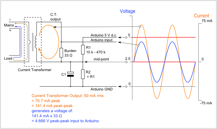
You are right you need more components. You need to add a dc voltage to the AC voltage so you dont have negative values.
Here you have an schematic that is very popular in internet.
The ZMPT101B as Costas says is also an option, I have one of those.
2 Likes
now you’re talking!
i understood this method. but your very first statement was a bit misleading (or incomplete):
based on the above, i thought - how the hack can this work? (because i assumed that the transformer and voltage divider forms the whole circuit)
but now we should stop talking these non blynk related stuff, before we encounter an angry @Gunner ![]()

;
2 Likes
can you share the Current measuring sensor that you are using for the Main house input
it shouldn’t be exceeding 30A other wise i will bankrupt 
WARNING TO ALL BLYNKERS: MESSING WITH MAINS ELECTRICITY CAN KILL
@scropion86 we live in a block of flats / apartments / condominiums and have a 45A supply but some of the properties in the block have a 30A supply. I think the Electric Company charge less for those with the lower maximum supply.
With sensors you get what you pay for from a couple of dollars to a couple of hundred dollars.
If it’s just current you require take a look at this thread, noting the maximum current for the 5A, 20A and 30A modules depending if you are using a 3.2 or 5.0V ADC https://community.blynk.cc/t/solved-acs712-voltage-amps-ghost-readings
The ACS712 is now discontinued and replaced with the ACS723 which is available in 5A, 10A, 20A and 40A. Even at 3.2V it should be good for +/- 32A.
The ACSXXX only provides current though so you would have to approximate PF. Many households have PF > 0.9 and that is why they don’t promote PF correction equipment to residential users.
Many parts of the world have legislated. some years ago, that all appliances over about 50W have PF correction built in.
1 Like
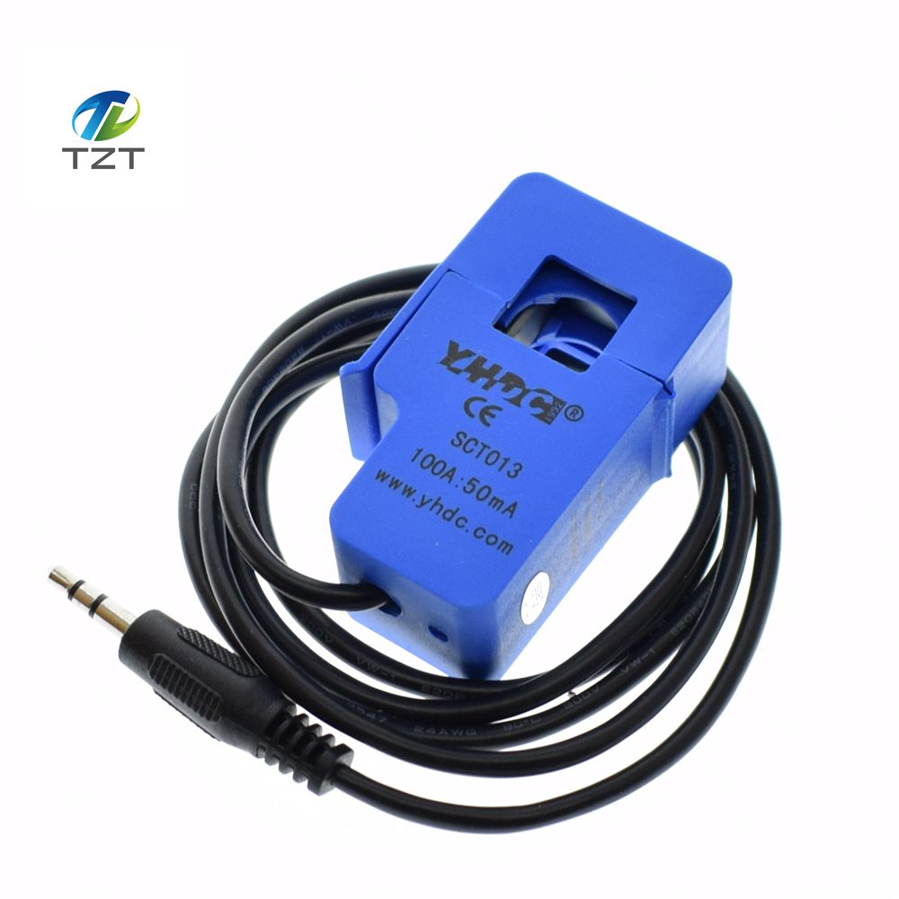
@scropion86 split core sensors are certainly safer for general end users and that particular model is quite popular.
Again that sensor only provides Amps and you then have to think about Volts for Energy cost metering etc.
isn’t this Ok for calculation ?
AC single phase amps to kilowatts calculation
The power P in kilowatts (kW) is equal to the power factor PF times the phase current I in amps (A), times the RMS voltage V in volts (V) divided by 1000:
P(kW) = PF × I(A) × V(V) / 1000
Yes but where are you going to get the PF value from with the current only sensors?