I’m guessing that this is to do with the fact that you aren’t using a proper FTDI and that you aren’t getting a proper power/ground supply to the TTL/USB adapter when not powering it from the PC.
However, your screenshot shows a baud rate of 9600 but my code uses 74880 for the serial monitor.
Sometimes. It requires the output of the Tracer to be set to a certain setting, and these aren’t very intuitive.
As you’ll see from my PCB, I’ve started using a 2-way relay board that is connected to D6 and D7, so I mostly use that approach now.
It can be, but the GND pin is common for the Wemos, Tracer, and TTL/USB adapter - all of them are interconnected.
Do you think it will work when I will be just sending data to Blynk and ThinkSpeak?
Yes, because the software I was using support communication up to 57600. Of course, to make it work, I reduced the baud rate of the Serial1 in the code to 9600.
So you control the load ON/OFF state via a relay and not by the device itself?
Paolo
Either approach works. I have two of these devices, one at home and one in Spain. The one in Spain was running on my original hardware and although I recently upgraded to my new PCB, I’ve not yet swapped over to using the relays to control the load power, as I need to make some changes to my load wiring first.
Hello Pete,
Just to let you know - I implemented the ThingSpeak and Blynk with your code and everything is working fine (when connected to an external power source).
When I try to get the Wemos powered directly from PIN 1 (orange) and GND (brown), the board got powered (I can see the onboard LED is on) but it doesn’t really work.
I really don’t understand the reason why it won’t work, I tried to connect directly to VIN and GND and also by attaching the wires to the power inlet jumper - neither way works.
Hi. I have just buy a epever duoracer for my motorhome and it would be amazing if I could monitoring the solar charger from my blynk app with a wemos d1 mini
Hello All,
I’m currently working on a project based on tekk and jaminNZx work.
I’ve managed to add quite more functionalities (more data to monitor, esp32 support, how-to guides, …) and I got few more I’d like to implement.
I guess it could be interesting to integrate my solution with yours.
I thought I’d add a little update on what I’m currently doing with my EPEVER solar controllers, and why.
Earlier this year the Tracer controller I have in Spain went faulty and started over-charging my batteries. Instead of the normal bell curve of charging current, which falls off after the battery SOC reaches 100%, the batteries were being charged at full power until the battery or controller temperature hit the preset maximum (around 70°C) then everything would shut down. This quite quickly wrecked the batteries, despite me turning my load on whenever the controller wasn’t shut down due to overheating.
I didn’t have anyone in Spain who could intervene and pull the fuses on the solar panel, so just had to watch the batteries being destroyed from 1000 miles away.
Having an almost identical setup at home in the UK I was able to investigate possible solutions, but unfortunately non of the things I tried were successful.
Instead, I decided to use a different approach for the future, as I realised that if I could run the EPEVER control software on a PC I’d be able to re-configure the controller to turn-off at a lower battery/controller temperature, and possibly reduce the charging cutoff voltage if this type of thing ever happened again.
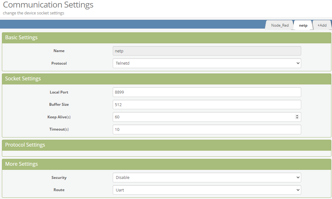
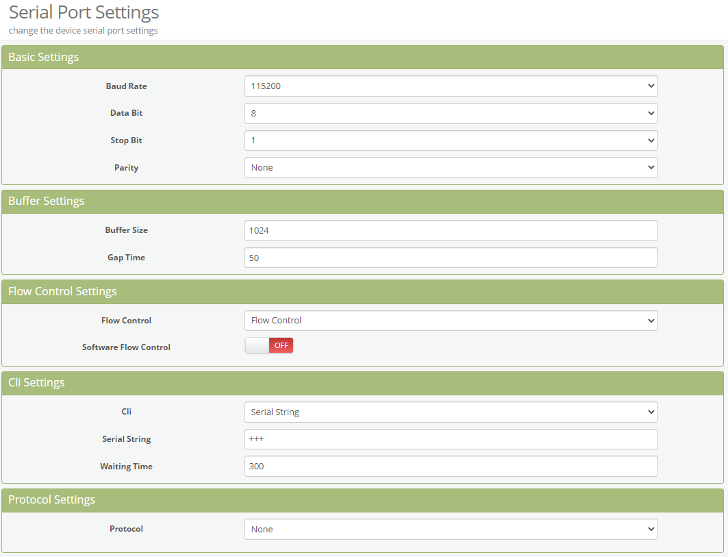
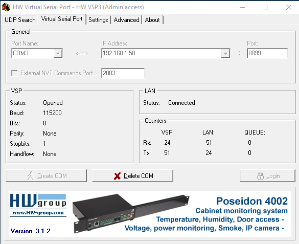
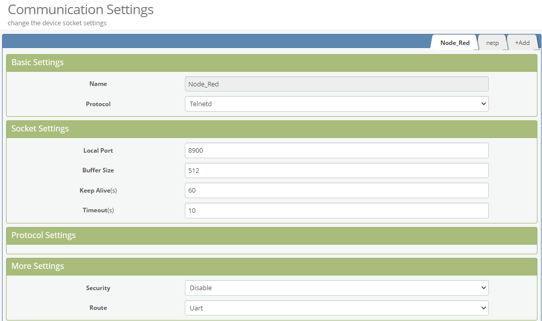
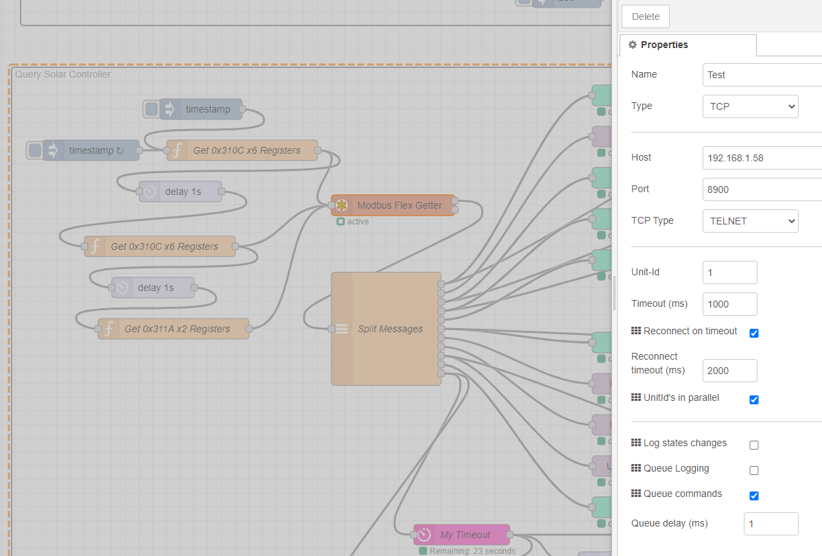
I decided to try using the Elfin EW-11 module and interrogate it via Node-Red. This worked well, and by installing a virtual serial port driver on a local PC I was also able to run the EPEVER management software as well.
After testing this on my UK setup I recently changed my Spanish setup to use the EW-11 instead of an ESP8266 based system. So far it’s working very well, and uses far less power than my old system, so should help reduce unwanted battery drain during the winter months.
Could you help advise about the configuration using Elfin EW-11 to run the epever management software? Let me know the virtual serial port software that you use as well.
I have Elfin EW-11 as well and already installing a virtual serial port on local PC but can not run epever software.
I was able to run the epever management software so well before using direct serial com to epever rs485 port . but i need communicate to epever software via wifi use EW-11 like your setup.
Hey guys, it’s me (the author of original post).
Just wanted to let you know, that I’ve totally given up using EPever controllers and I’m now using two Victron MPPT 75/15 as it turned out the EPevers are very faulty. (I have 3 faulty EPevers, each with different issue at my shack).
The Victron Energy 75/15 MPPTs have built in Bluetooth which I can use to connect and monitor from the Android phone and it also has a Serial out, for which already exists many integrations on Github (like ESPHome i.e.).
My suggestion is not to buy these controllers, I have bad experience.
Have a nice day everyone!
The IP address and port obviously has to match the settings for your EW-11.
The VCP driver creates a tray icon in Windows and this can be used to start/stop and configure the settings (the port has to be stopped (deleted) for settings to be changed). If you check the “Create VSP Port when HW VSP Start-up” option in the Settings tab - and save the settings to the .INI file - then the virtual com port will start automatically when you launch the VSP driver, otherwise you will need to click the Create COM button.
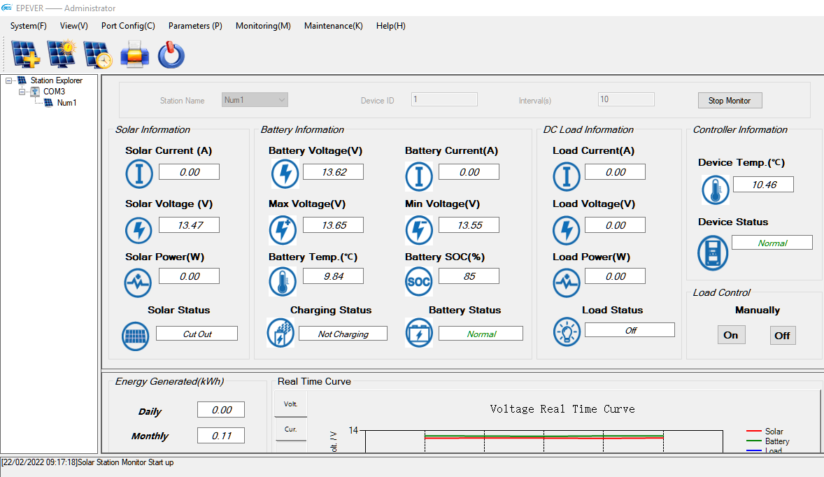
You then have to configure the EPEVER Solar Station Monitor software to use the same com port and baud rate etc, and click the “Start Monitoring” button…
I only tend to use the EPEVER software if I need to change a configuration setting - as mention in an earlier post, and if I was going to do that then I’d probably stop Node-Red polling the EW-11 first, so that I had uninterrupted access to the solar charge monitor via the virtual COM port and the EW-11.
One thing to watch out for is that if you create the VCP on an available COM port on your PC (COM3 in my case) then stop the VCP and plug-in another device which gets assigned as the same COM port number then it will cause problems when you try to fire-up the VCP. If you change the VCP COM port number to get around tis then you also have to change the COM port that’s used in the EPEVER monitoring software.