Hello, I am very happy with this post. I found what I was looking for for a long time, but I have a question, can this work be done with inverter voltronic?
Does it use RS485?
Do you have access to the communication protocols?
Pete.
Hello Pete Thank you for the help Yes use rs-485 access to communication protocol
In that case, the solutions discussed in this topic should work.
I’m my experience, it’s best not to poll the device too frequently, and best not to try to read too many registers at the same time.
Pete.
Thank you again, I will give it a try
I have tried this code but no result
#define BLYNK_TEMPLATE_ID "TMPLFa3t-1VM"
#define BLYNK_DEVICE_NAME "inverter"
#define BLYNK_AUTH_TOKEN "7Zs485KmXnsfG63NgtQqmekTNd2S4UhW"

#define BLYNK_PRINT Serial
#include <ESP8266WiFi.h>
#include <BlynkSimpleEsp8266.h>
 #include <ModbusMaster.h>      //https://github.com/4-20ma/ModbusMaster/
 #include <ESP8266WiFi.h>
 #include <SimpleTimer.h>      // Non-blocking timer
 #include <PubSubClient.h>     // https://github.com/knolleary/pubsubclient

 #define MAX485_DE       D2
 #define MAX485_RE       D1

 #define PANEL_VOLTS     0x00
 #define PANEL_AMPS      0x01
 #define PANEL_POWER_L   0x02
 #define PANEL_POWER_H   0x03
 #define BATT_VOLTS      0x04
 #define BATT_AMPS       0x05
 #define BATT_POWER_L    0x06
 #define BATT_POWER_H    0x07
 #define LOAD_VOLTS      0x0C
 #define LOAD_AMPS       0x0D
 #define LOAD_POWER_L    0x0E
 #define LOAD_POWER_H    0x0F

// Added by PK...
 #define CONTROL_TEMP   0x11
 #define BATT_TEMP      0x10 // Remote Battery Temp. If 0x1B not working then try 0x10
 #define BATT_SOC       0x1A // Battery State of Charge (Percentage)

// #define HB D4

// Initialise ModbusMaster object
ModbusMaster node;

// Initialise the timer object
SimpleTimer timer;

char auth[] = BLYNK_AUTH_TOKEN;
char ssid[] = "ULTRA ARDUINO 6";
char pass[] = "qwerty123";

void setup()
{
  Blynk.begin(auth, ssid, pass);
  Serial1.begin (74880);
  Serial1.println("Serial1 Initialised");

  Serial.begin(115200); // DO NOT CHANGE!

  pinMode(MAX485_RE, OUTPUT);
  pinMode(MAX485_DE, OUTPUT);
  // Init in receive mode
  digitalWrite(MAX485_RE, 0);
  digitalWrite(MAX485_DE, 0);

  // EPEver Device ID 1
  node.begin(1, Serial);

  // Callbacks
  node.preTransmission(preTransmission);
  node.postTransmission(postTransmission);

timer.setInterval(2000, readMODBUS);
 }

 void readMODBUS()
{
  uint8_t result;

  // Read 20 registers starting at 0x3100)
  node.clearResponseBuffer();
  result = node.readInputRegisters(0x3100, 20);

  if (result == node.ku8MBSuccess)
  {
    float pV = node.getResponseBuffer(PANEL_VOLTS)/100.0f;
    float pI = node.getResponseBuffer(PANEL_AMPS)/100.0f;
    float pP = (node.getResponseBuffer(PANEL_POWER_L) |
                    (node.getResponseBuffer(PANEL_POWER_H) << 8))/100.0f;

    float bV = node.getResponseBuffer(BATT_VOLTS)/100.0f;
    float bI = node.getResponseBuffer(BATT_AMPS)/100.0f;
    float bP = (node.getResponseBuffer(BATT_POWER_L) |
                    (node.getResponseBuffer(BATT_POWER_H) << 8))/100.0f;

    float lV = node.getResponseBuffer(LOAD_VOLTS)/100.0f;
    float lI = node.getResponseBuffer(LOAD_AMPS)/100.0f;
    float lP = (node.getResponseBuffer(LOAD_POWER_L) |
                    (node.getResponseBuffer(LOAD_POWER_H) << 8))/100.0f;

// Added by PK
    float bT = node.getResponseBuffer(BATT_TEMP)/100.0f;
    float bSOC = node.getResponseBuffer(BATT_SOC)/100.0f;

    float cT = node.getResponseBuffer(CONTROL_TEMP)/100.0f;


    Serial1.print("VPanel: ");
    Serial1.println(pV);
    Serial1.print("IPanel: ");
    Serial1.println(pI);
    Serial1.print("PPanel: ");
    Serial1.println(pP);
    Serial1.println();
    Serial1.print("VBatt: ");
    Serial1.println(bV);
    Serial1.print("IBatt: ");
    Serial1.println(bI);
    Serial1.print("PBatt: ");
    Serial1.println(bP);
    Serial1.print("TBatt: ");
    Serial1.println(bT);
    Serial1.print("SOC  : ");
    Serial1.println(bSOC);
    Serial1.println();
    Serial1.print("VLoad: ");
    Serial1.println(lV);
    Serial1.print("ILoad: ");
    Serial1.println(lI);
    Serial1.print("PLoad: ");
    Serial1.println(lP);
    Serial1.println();
    Serial1.print("CTemp: ");
    Serial1.println(cT);
    Serial1.println();
    Serial1.println();
    Blynk.virtualWrite(V0,pV);
    Blynk.virtualWrite(V1,pI);
    Blynk.virtualWrite(V2,pP);
    Blynk.virtualWrite(V3,bV);
    Blynk.virtualWrite(V4,bI);
    Blynk.virtualWrite(V5,bP);
    Blynk.virtualWrite(V6,lV);
    Blynk.virtualWrite(V7,lI);
    Blynk.virtualWrite(V8,lP);
    Blynk.virtualWrite(V9,bT);
    Blynk.virtualWrite(V10,bSOC);
    Blynk.virtualWrite(V11,cT);

  } else {
    Serial1.print("Bad Read, ret val:");
    Serial1.println(result, HEX);

    // Result codes:
    // 00 Success
    // 01 Illegal function Error
    // 02 Illegal Data Address Error
    // 03 Illegal Data Value Error
    // E0 Invalid Response Slave ID Error
    // E1 Invalid Response Function Error
    // E2 Response Timed-Out Error
    // E3 Invalid Response CRC Error
   }
}


void loop()
{
  Blynk.run();
  timer.run();
  }

void preTransmission()
{
  digitalWrite(MAX485_RE, 1);
  digitalWrite(MAX485_DE, 1);
}

void postTransmission()
{
  digitalWrite(MAX485_RE, 0);
  digitalWrite(MAX485_DE, 0);
}
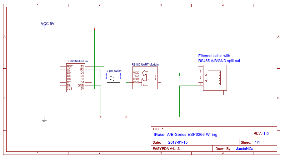
I’m not sure how you expect us to be able to assist you when we don’t have access to the same inverter hardware as you, and you haven’t shared any information about the wiring and baud rate of the inverters’s interface, the registers that the inverter uses for each parameter, and the protocol that the inverter expects when it’s registers are queried.
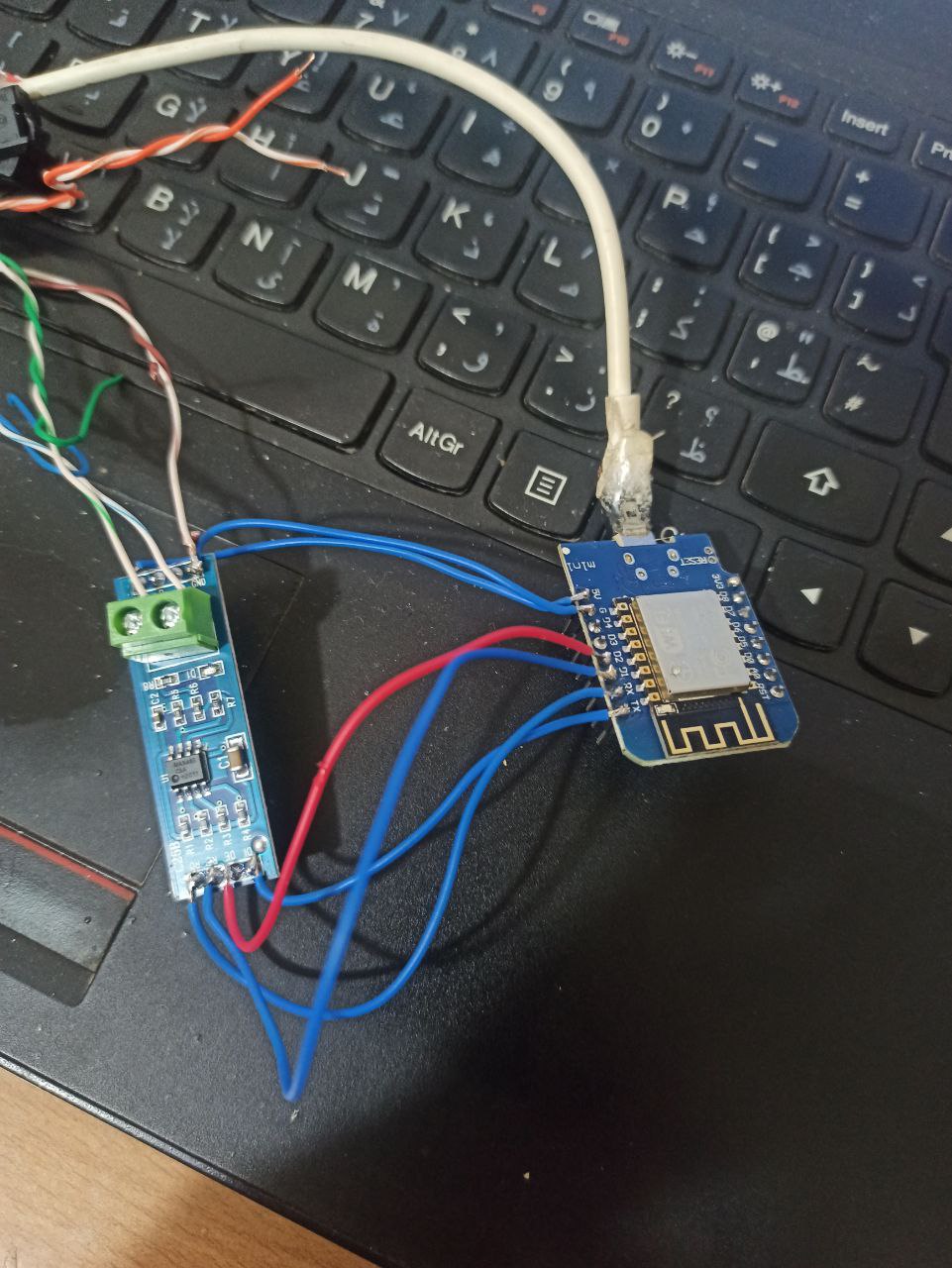
I’m also a great believer in removing as may potential variables and failure points from the process when testing. Judging by the state of your wiring in the images, you could have poor or intermittent connections, or mis-wiring die to the way in which you’ve hooked-up the components with the same coloured wires. Some of those solder joints look very dodgy to me.
Pete.
Unfortunately, I don’t know how to contact him
So when I asked…
I guess that in reality the answer from you should have been “No” ?
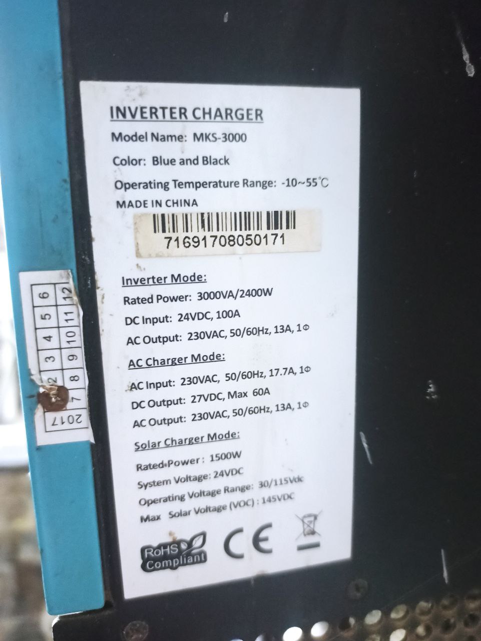
Looking at the online manuals, it appears that your device uses RS232 communication, so the answer to that question should probably have been “No” as well.
Pete.
Thank you Pete for the help. Can you send me the brochures so I can see them? I looked for them and couldn’t find them
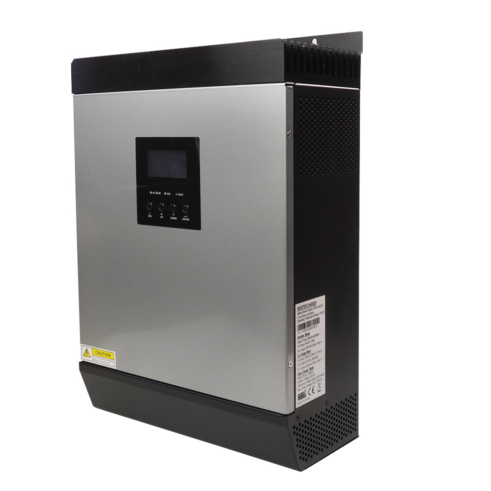
But my mks-3000 inverter only has an ethernet port
https://www.suncityitalia.com/wp-content/uploads/2016/08/MKS-MKS-1-5KVA-manual-20160301.pdf
It has an RJ45 socket, which is the same as the connector used for Ethernet cables, but it’s not an Ethernet socket, it’s an RS232 port.
Pete.
I’ve moved these posts from the original topic into a new one, so that the original topic doesn’t get dragged off-topic.
Pete.