ESP8266 (NoceMCU), EPEver Tracer A and MAX485 module

Hey guys,
I’m new here.

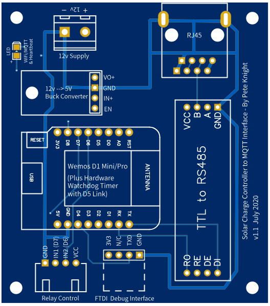
My setup is: ESP8266 (NoceMCU), EPEver Tracer A and MAX485 module.

I’ve tried to make a upgraded version of jaminNZx’s Tracer-RS485-Modbus-Blynk repo, because I wasn’t getting some of the data out from the Tracer. For example, load current and load power were always 0.00.

I also tried to add option to turn the load ON/OFF from the Blynk app, unsuccessfully for now.

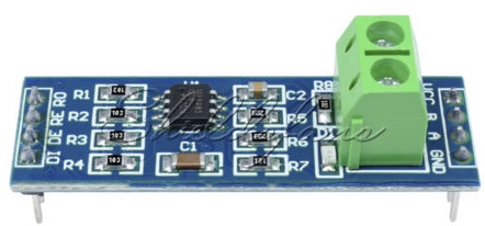
Anyhow, I’ve used the cheapo MAX485 module, and it works flawlessly.
Exactly this one:
max485_module

And I’ve also tried to utilize RXD2 and TXD2 to communicate with the solar module, hoping to avoid the need of disconnecting MAX485’s serial pins from the ESP8266 on every upload.

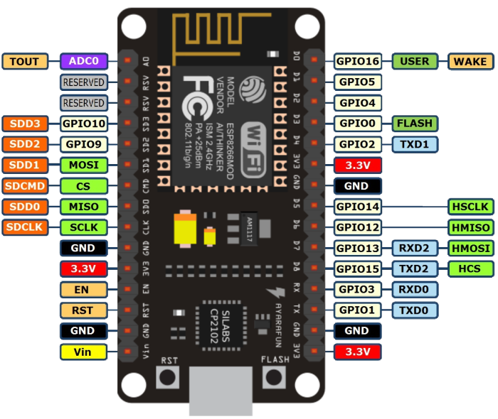
According to ESP8266 official documentation about Serial, when you call Serial.swap() after Serial.begin your Serial pins change from GPIO1 (TX) and GPIO3 (RX) to GPIO13 (D7) and GPIO15 (D8).


I haven’t been successful at this, because no matter what I did, even when Tracer was connected to GPIO13 (D7) / RXD2 and GPIO15 (D8) / TXD2, I wasn’t able to upload code until I disconnected the MAX485 from these pins.

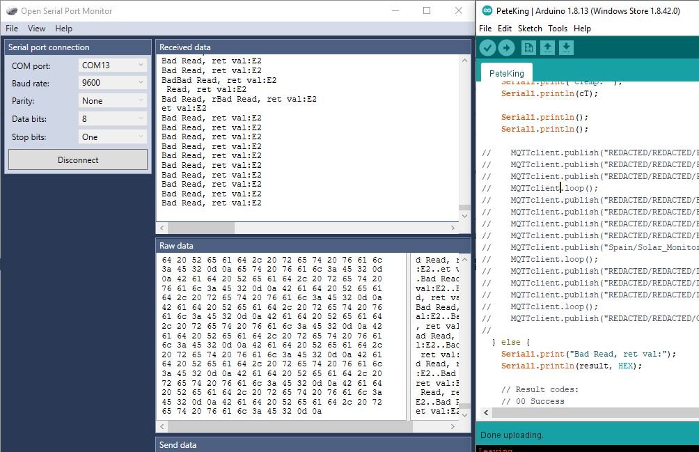
What I also wanted to accomplish by this is that you would also get USB serial debug messages (also Tracer output values) and meanwhile it wouldn’t collide with the Modbus communication.

I’ve also added preTransmission() and postTransmission() callback’s code to trigger the DE / RE pins of the MAX485.

Next, I’ve found a bug that could cause the Tracer become unresponsive in nextRegistryNumber() function:

// function to switch to next registry
void nextRegistryNumber() {
  // better not use modulo, because after overlow it will start reading in incorrect order
  currentRegistryNumber++;
  if (currentRegistryNumber >= ARRAY_SIZE(Registries)) {
    currentRegistryNumber = 0;
  }
}

I’ve also find some bugs in the ModbusMaster library, because the UART HW buffer length is hardcoded to 64 bytes there, and ESP8266 has 256 byte hardware buffer. I think this has also made problems reading correct values. I considered to rewrite also the ModbusMaster library, but haven’t time for that…

Another thing that I was trying is to use SoftwareSerial for ESP8266, which would in other way work just ok, (it does115200 baud pretty well), but again, the way the ModbusMaster library is written, it’s unable to work with SoftwareSerial, it’s dependent on HW UART, it’s harcoded there. So again, the only solution for this would be to rewrite whole ModbusMaster Arduino library.

I also added hooks for ArduinoOTA, because it weren’t implemented in the original repo, and upload over the air didn’t work either.

Another thing that I think is a bug I found, in AddressRegistry_3100 function readInputRegisters reads only 7 registers, which are 16-bit (uint16_t to be more specific), but in following lines it reads the output buffer registers at position 0x11 etc… This would mean we would need to read at least 0x11 = 17 DEC 16-bit registers.

Meanwhile I’ve got to that state with my branch, that I was able to read all values successfully, BUT then I’ve tried to “just improve the code a little bit” and I accidentally :smiley: rewrote the whole logic and now it doesn’t work “very well”.

I’ve got many SBCs in my hamshack, so maybe I will write just some Python script to upload the data to Blynk.

My modified repo is here - branch name code-fixes-by-tekk.

Any ideas and suggestions are welcome.

3 Likes

Welcome.

I wasn’t sure if you were looking for assistance or showing your project… either way I moved your post into its own topic for further discussion.

Thanks Gunner,
well… kinda both.

I finally managed to get my project working.
I commited the changes into my branch.

I just can’t verify if the Load Power and Load Current is showing because the weather is horrible and my batteries are drained.

Hi all. I’m working on this as well. I have one remaining issue that I wanted to see if others have hit related to load control.

In order to control the load output (on/off) on the charge controller we can either use load test by writing single coil 0x06, or manual by writing single coil 0x02.

For either of these methods of load control I find that neither will work unless I first place the tracer into test mode (write 0x05 = 1) or manual mode (write 0x01 = 1). As soon as I perform one of these writes two things appear to happen:

  • The load control starts working
  • Reading registers stops working correctly. Some registers such as the ones starting at 0x3100 and 0x310D start failing

These register reads fail consistently and continuously until the tracer is completely powered off and back on.

Has anyone else seen this and found a workaround?

1 Like

Your blynk project has been deleted :(…Please share again!

hi do your have the connection diagram of the max485 and esp8266. thanks for sharing.

I’m using this cheapo module and it works quite fine. It’s powered from +5V from ESP8266, and wired as following:

  • MAX485 module <-> ESP8266
    • DI -> D10 / GPIO1 / TX
    • RO -> D9 / GPIO3 / RX
    • DE and RE are interconnected with a jumper and then connected do eighter pin D1 or D2
    • VCC to +5V / VIN on ESP8266
  • Tracer A/B MPPT Controller Ethernet cable <-> MAX485
    • Ethernet green, pin 5 -> A
    • Ethernet blue, pin 3 -> B
    • Ethernet brown, pin 7 -> GND on module and ESP8266 GND pin
      • -> to prevent ground loops - important!

I bought one of these charge controllers earlier this year and struggled to get extract some of the data registers that were documented as being available.
I spent a LOT of time looking at other people’s code and reading different versions of the documentation. it quickly became clear that the latest documentation has some errors and omissions, and that earlier versions were more complete, but less easy to follow.

Things like the battery State of Charge value, and remote/internal temperature values were particularly difficult to extract. I also wanted to be able to switch the load on and off via a command, which was something that seems as though it should be possible, but I couldnt find any code examples.

The other issue I found was that reading too many registers at one time lead to incomplete data, or a high rate of read errors.

Here’s my function that’s used to read the registers:

void readMODBUS()
{
// Result codes:
// 00 Success
// 01 Illegal function Error
// 02 Illegal Data Address Error
// 03 Illegal Data Value Error
// E0 Invalid Response Slave ID Error
// E1 Invalid Response Function Error
// E2 Response Timed-Out Error
// E3 Invalid Response CRC Error
   
  uint8_t result;

  // Read 8 registers starting at 0x3100)
  node.clearResponseBuffer();
  result = node.readInputRegisters(0x3100, 8);

  if (result == node.ku8MBSuccess)
  {
    pV = node.getResponseBuffer(PANEL_VOLTS)/100.0f;
    pI = node.getResponseBuffer(PANEL_AMPS)/100.0f;
    pP = (node.getResponseBuffer(PANEL_POWER_L)|(node.getResponseBuffer(PANEL_POWER_H) << 8))/100.0f;

    bV = node.getResponseBuffer(BATT_VOLTS)/100.0f;
    bI = node.getResponseBuffer(BATT_AMPS)/100.0f;

    bP = (node.getResponseBuffer(BATT_POWER_L) |
                    (node.getResponseBuffer(BATT_POWER_H) << 8))/100.0f;
  }
  else
  {
      Serial1.print("Read register 0x3110 failed! - Error Code = ");
      Serial1.println(result, HEX);     
  }


  // Read 4 registers starting at 0x310C)
  node.clearResponseBuffer();
  result = node.readInputRegisters(0x310c, 4);

  if (result == node.ku8MBSuccess)
  {
    lV = node.getResponseBuffer(LOAD_VOLTS)/100.0f;
    lI = node.getResponseBuffer(LOAD_AMPS)/100.0f;
    lP = (node.getResponseBuffer(LOAD_POWER_L) |
                    (node.getResponseBuffer(LOAD_POWER_H) << 8))/100.0f;
  }
  else
  {
      Serial1.print("Read register 0x310C failed! - Error Code = ");
      Serial1.println(result, HEX);
  }

  // Read 2 registers starting at 0x3110)
  node.clearResponseBuffer();
  result = node.readInputRegisters(0x3110, 2);

  if (result == node.ku8MBSuccess)
  {
    bT = node.getResponseBuffer(BATT_TEMP)/100.0f;
    cT = node.getResponseBuffer(CONTROL_TEMP)/100.0f;    

  }
   else
  {
      Serial1.print("Read register 0x3111 failed! - Error Code = ");
      Serial1.println(result, HEX);
  }

  // Read 1 register starting at 0x311A)
  node.clearResponseBuffer();
  result = node.readInputRegisters(0x311A, 1);

  if (result == node.ku8MBSuccess)
  {
    bSOC = node.getResponseBuffer(BATT_SOC)/1.0f;
  }
   else
  {
      Serial1.print("Read register 0x3111 failed! - Error Code = ");
      Serial1.println(result, HEX);
  }
                 
                    
    Serial1.print("VPanel: ");
    Serial1.println(pV);
    Serial1.print("IPanel: ");
    Serial1.println(pI);
    Serial1.print("PPanel: ");
    Serial1.println(pP);
    Serial1.println();

    Serial1.print("VBatt: ");
    Serial1.println(bV);
    Serial1.print("IBatt: ");
    Serial1.println(bI);
    Serial1.print("PBatt: ");
    Serial1.println(bP);                    
    Serial1.print("TBatt: ");
    Serial1.println(bT);
    Serial1.print("SOC  : ");
    Serial1.println(bSOC);         
    Serial1.println();
    
    Serial1.print("VLoad: ");
    Serial1.println(lV);
    Serial1.print("ILoad: ");
    Serial1.println(lI);
    Serial1.print("PLoad: ");
    Serial1.println(lP);   
    Serial1.println();
    Serial1.print("CTemp: ");    
    Serial1.println(cT);    
    
    Serial1.println();
    Serial1.println();

    }
} // End of void ReadMODBUS

and this is my function to toggle the load power on/off (requiers being called with a paramerer of 0 to turn the load off and 1 to turn it on [setOutputLoadPower(1); or setOutputLoadPower(1);]

uint8_t setOutputLoadPower(uint8_t state)
{
  
  Serial1.print("Writing coil 0x0002 value to: ");
  Serial1.println(state);

  delay(10);
  // Set coil at address 0x0002 (Force the load on/off)
  node.writeSingleCoil(0x0001, 1);
  result = node.writeSingleCoil(0x0002, state);  

  if (result == node.ku8MBSuccess)
  {
    node.getResponseBuffer(0x00);
    Serial1.println("Success.");
  }
  return result;
}

Pete.

1 Like

Dear Pete,
I’m struggling to get any data from my Tracer. Could you please share your complete code so I could try to use it on my Tracer?

Best regards, Paolo

My code uses MQTT messaging, so isn’t really going to help you.

What hardware setup do you have, what code are you running, and what results are you seeing?

Pete.

Dear Pete,

Basically, I tried to implement the project of tekk from the first post.
The only difference is I’m using the Wemos D1R2 instead of NodeMCU as he did. So I connected the Tracer with an MAX485 module to the Wemos.

On the Wemos I had tried using hardware serial as you tekk did (attaching the DI -> D10 / GPIO1 / TX and the RO -> D9 / GPIO3 / RX as in your manual), without a success - I’m getting always the “Read register 0x311x failed!” I tried also to comment on all the serial.print commands (as I supposed that maybe the serial communication of the PC <-> Wemos is interfering with the communication between the Wemos and MAX485USB - anyway I can’t get the data on the Blynk app (I see the device is online but all the reading stays at 0.0).
I tried to use a software serial instead of the hardware serial, but also without success.
I tried to declare the pins by D0, D1, D2, D3 and by GPIO coding (16, 5, 4, 0) both without success (both on hardware (for DE and RE) and software serial(for all the pins)) without success.

What hardware setup did you use?
Paolo

I use a Wemos D1 Mini and a custom PCB that holds the Wemos, the MAX485, power supply, RJ45 socket etc.
I agree that using the serial port for debug messages is a bad move, and I use Serial1 (which is Tx only, but that’s fine for debugging). This requires an FTDI adapter to use be able to be able to view debug messages, but that’s fine for me on the odd occasions I need to do this.

SoftwareSerial isn’t reliable at speeds above 9600, so is no use for the 115200 required for the Tracer.

Pete.

I have an almost identical hardware setup as yours (the only difference is that I don’t have an FDI adapter, I probably will take one), and using the tekk code I can’t get the readings. I managed to take the reading from the Tracer using the original CC-USB-4S485-150U EPever cable connected to the PC and also connected to the Raspberry, so the Tracer should be OK.

Would you be willing to give me the code so I can try to read the data with the Wemos? In fact, I don’t really mind debugging as long as I get the reading from the Tracer.
Best regards, Paolo

My current code is split into 12 tabs in my Arduino IDE project, so isn’t really suitable for sharing here.

However, I do have some earlier code which worked, but not as well as the code I posted above because trying to read all the registers at once doesn’t work well.

I’d suggest that you just try reading one group of registers (such as the 8 registers starting at 0x3100) as a test.

But, first things first, are you powering your MAX485 module with 5V from your Wemos? (Powering it from the Tracer didn’t work for me)
Are the lights on on the MAX485 and does one of then flash when you try to take a reading?

Also, without an FTDI, debugging is very difficult! The Rx pin on the FTDI connects to pin D4 on the D1 Mini (GPIO2) and the GND connection should connect to the GND on the board.

Here’s my basic (early) code…

#include <ModbusMaster.h>      //https://github.com/4-20ma/ModbusMaster/
 #include <ESP8266WiFi.h>
 #include <SimpleTimer.h>      // Non-blocking timer
 #include <PubSubClient.h>     // https://github.com/knolleary/pubsubclient
 
 #define MAX485_DE       D2
 #define MAX485_RE       D1

 #define PANEL_VOLTS     0x00
 #define PANEL_AMPS      0x01
 #define PANEL_POWER_L   0x02
 #define PANEL_POWER_H   0x03
 #define BATT_VOLTS      0x04
 #define BATT_AMPS       0x05
 #define BATT_POWER_L    0x06
 #define BATT_POWER_H    0x07
 #define LOAD_VOLTS      0x0C
 #define LOAD_AMPS       0x0D
 #define LOAD_POWER_L    0x0E
 #define LOAD_POWER_H    0x0F

// Added by PK...
 #define CONTROL_TEMP   0x11
 #define BATT_TEMP      0x10 // Remote Battery Temp. If 0x1B not working then try 0x10
 #define BATT_SOC       0x1A // Battery State of Charge (Percentage)

// #define HB D4

// Initialise ModbusMaster object
ModbusMaster node;

// Initialise the timer object
SimpleTimer timer;


const char* ssid = "REDACTED";
const char* pass = "REDACTED";

IPAddress ip            (REDACTED, REACTED, REDACTED, REACTED);          //Static IP Address for the device
IPAddress gateway       (REDACTED, REACTED, REDACTED, REACTED);
IPAddress subnet        (REDACTED, REACTED, REDACTED, REACTED);

IPAddress MQTTserver    (REDACTED, REACTED, REDACTED, REACTED);       // IP Address for the MQTT Server...

WiFiClient My_WiFi_Client;

PubSubClient MQTTclient(My_WiFi_Client);


void setup()
{
  WifiConnect(); 

  MQTTclient.setServer(MQTTserver, REDACTED);
  MQTTconnect();

  
//  WiFi.begin(ssid, password);

  Serial1.begin (74880);
  Serial1.println("Serial1 Initialised");
  
  Serial.begin(115200); // DO NOT CHANGE!

  pinMode(MAX485_RE, OUTPUT);
  pinMode(MAX485_DE, OUTPUT);
  // Init in receive mode
  digitalWrite(MAX485_RE, 0);
  digitalWrite(MAX485_DE, 0);

  // EPEver Device ID 1
  node.begin(1, Serial);

  // Callbacks 
  node.preTransmission(preTransmission);
  node.postTransmission(postTransmission);

timer.setInterval(2000, readMODBUS);

}


void readMODBUS()
{
  uint8_t result;

  // Read 20 registers starting at 0x3100)
  node.clearResponseBuffer();
  result = node.readInputRegisters(0x3100, 20); 

  if (result == node.ku8MBSuccess)
  {
    float pV = node.getResponseBuffer(PANEL_VOLTS)/100.0f;
    float pI = node.getResponseBuffer(PANEL_AMPS)/100.0f;
    float pP = (node.getResponseBuffer(PANEL_POWER_L) |
                    (node.getResponseBuffer(PANEL_POWER_H) << 8))/100.0f;

    float bV = node.getResponseBuffer(BATT_VOLTS)/100.0f;
    float bI = node.getResponseBuffer(BATT_AMPS)/100.0f;
    float bP = (node.getResponseBuffer(BATT_POWER_L) |
                    (node.getResponseBuffer(BATT_POWER_H) << 8))/100.0f;

    float lV = node.getResponseBuffer(LOAD_VOLTS)/100.0f;
    float lI = node.getResponseBuffer(LOAD_AMPS)/100.0f;
    float lP = (node.getResponseBuffer(LOAD_POWER_L) |
                    (node.getResponseBuffer(LOAD_POWER_H) << 8))/100.0f;

// Added by PK
    float bT = node.getResponseBuffer(BATT_TEMP)/100.0f;
    float bSOC = node.getResponseBuffer(BATT_SOC)/100.0f;
    
    float cT = node.getResponseBuffer(CONTROL_TEMP)/100.0f;   
                    
                    
    Serial1.print("VPanel: ");
    Serial1.println(pV);
    Serial1.print("IPanel: ");
    Serial1.println(pI);
    Serial1.print("PPanel: ");
    Serial1.println(pP);
    Serial1.println();

    Serial1.print("VBatt: ");
    Serial1.println(bV);
    Serial1.print("IBatt: ");
    Serial1.println(bI);
    Serial1.print("PBatt: ");
    Serial1.println(bP);                    
    Serial1.print("TBatt: ");
    Serial1.println(bT);
    Serial1.print("SOC  : ");
    Serial1.println(bSOC);         
    Serial1.println();
    
    Serial1.print("VLoad: ");
    Serial1.println(lV);
    Serial1.print("ILoad: ");
    Serial1.println(lI);
    Serial1.print("PLoad: ");
    Serial1.println(lP);   
    Serial1.println();
    Serial1.print("CTemp: ");    
    Serial1.println(cT);    
    
    Serial1.println();
    Serial1.println();

    MQTTclient.publish("REDACTED/REDACTED/Panel_Output_Voltage",String(pV).c_str(),true);   
    MQTTclient.publish("REDACTED/REDACTED/Panel_Output_Current",String(pI).c_str(),true);   
    MQTTclient.publish("REDACTED/REDACTED/Panel_Output_Wattage",String(pP).c_str(),true);
    MQTTclient.loop();    
    MQTTclient.publish("REDACTED/REDACTED/Battery_Voltage",String(bV).c_str(),true);   
    MQTTclient.publish("REDACTED/REDACTED/Battery_Charge_Current",String(bI).c_str(),true);   
    MQTTclient.publish("REDACTED/REDACTED/Battery_Charge_Wattage",String(bP).c_str(),true);
    MQTTclient.publish("REDACTED/REDACTED/Battery_Temperature",String(bT).c_str(),true);      
    MQTTclient.publish("Spain/Solar_Monitor/Battery_SOC",String(bSOC).c_str(),true);
    MQTTclient.loop();   
    MQTTclient.publish("REDACTED/REDACTED/Load_Voltage",String(lV).c_str(),true);   
    MQTTclient.publish("REDACTED/REDACTED/Load_Current",String(lI).c_str(),true);
    MQTTclient.publish("REDACTED/REDACTED/Load_Wattage",String(lP).c_str(),true);   
    MQTTclient.loop();   
    MQTTclient.publish("REDACTED/REDACTED/Controller_Temerature",String(cT).c_str(),true);           
    
  } else {
    Serial1.print("Bad Read, ret val:");
    Serial1.println(result, HEX);

    // Result codes:
    // 00 Success
    // 01 Illegal function Error
    // 02 Illegal Data Address Error
    // 03 Illegal Data Value Error
    // E0 Invalid Response Slave ID Error
    // E1 Invalid Response Function Error
    // E2 Response Timed-Out Error
    // E3 Invalid Response CRC Error
   }
}


void loop()
{
  timer.run();

  if (!MQTTclient.connected())
  {
    MQTTconnect();
  }
  MQTTclient.loop();

    if(WiFi.status() != WL_CONNECTED)
  {
    WifiConnect(); 
  }
}

void WifiConnect()
{
  WiFi.begin(ssid, pass);
  WiFi.config(ip, gateway, subnet);
  WiFi.mode(WIFI_STA);

  while (WiFi.status() != WL_CONNECTED)
  {
    delay(500);
    Serial1.print(".");
  }
} // End of void WiFiConnect


void MQTTconnect()
{
  // Loop until we're connected
  while (!MQTTclient.connected())
  {
    int reason=MQTTclient.state();
    Serial1.print("MQTT Disconnection reason = ");
    Serial1.println(reason);  
    
    
    Serial1.print(F("Attempting MQTT connection..."));
    // Attempt to connect
    if (MQTTclient.connect("REDACTED", "REDACTED", "REDACTED"))
    {
      Serial1.println(F("MQTT Connected"));        
      // Once connected, publish an announcement...
      MQTTclient.publish("REDACTED/REDACTED/REDACTED","ALIVE");      
      MQTTclient.loop();
    }
      // ... and subscribe or re-subscribe

    else  // We get here if the MQTT Connect failed....
    {
      Serial1.print(F("failed, rc="));
      Serial1.print(MQTTclient.state());
      Serial1.println(F(" try again in 1 seconds"));
      // Wait 1 second before retrying
      delay(1000);
    }
  }  
} // End of function MQTTconnect


void preTransmission()
{
  digitalWrite(MAX485_RE, 1);
  digitalWrite(MAX485_DE, 1);
}

void postTransmission()
{
  digitalWrite(MAX485_RE, 0);
  digitalWrite(MAX485_DE, 0);
}

Pete.

1 Like

Thanks for the code. As of now, I don’t have the FTDI I will have to modify your code and try to parse the data to ThingSpeak or Blynk.
Regarding the FTDI, what type are you using? There are different types so I’m not sure what type can work. Are one of these two devices suitable?

Regarding powering the MAX485, I use Wemos 5V and GND pins, powering from the tracer was the next step in my mind (I checked and the first 2 wire are giving 4.5V the orange/white and orange wires of the ethernet cable).

On my MAX485 there is only one LED and when I connect the 5V and GND it’s steady lightning no mether if I try to get the reading or not. I can see a flashing only when I connect the pins DI, DE, DE, RO, and GND to the Wemos and not connecting the 5V. It’s that “normal” behaving or not?

Paolo

I use this type of FTDI…

I think my MAX485 has a power and “activity” LEDs and that the “activity” one flashes when a reading is taken, but I’d need to check.

Pete.

Just checked, and the 485 modules that I’m currently using just have a power LED.

Another thought, are you sure that you’ve connected the RJ45 connections correctly?

Pete.

Do you mean the RJ45 to the A and B of the MAX485? I was forwarding the instruction of this PDF, nevertheless, I did try to invert the wire - no success.

I suppose this LED on your MAX485 is always on as mine, am I right?

So I was thinking about how to connect to the Serial1, and not to wait for the FDTI adapter from China (because it will take more than a month to come to my country), and in the end, I figured out I can use the original CC-USB-4S485-150U EPever cable for debugging :slight_smile:

I connected to the D4 and GND as you instructed (to the CC-USB) and I can read the Serial1.

Now, I did try to install this MQTT client to my PC (mosquitto) and to get the Wemos connected to it, but as the MQTT and this mosquitto it’s a bit confusing to me I ended commenting the whole part regarding the MQTT in your code.
If I understand well you were using the MQTT just to communicate (forward) the result to “into the world” - am I right? Anyhow, I don’t need this for this my test purpose.
As my solar charge controller is on a remote site, I can’t test it today. If the weather condition will be OK I will test it Friday evening and let you know the result.

One more question - do you connect as follow:
DI of the MAX485 to the TX of the Wemos and
RO of the MAX485 to the RX of the Wemos?

Thank you very much for now.
Paolo

Yes, that diagram at the end is correct. However, I’m assuming that you’ve chopped-up a network cable to wire this up, so you should take a very careful look at the colours of the wires as they are connected in the plug, and ensure that you are actually using the correct ones at the other end.

Yes.

Good thinking!

That’s correct. I have a a Raspberry Pi running Mosquitto and Node-Red. I have the Blynk plug-in for Node-Red installed, which gives me my Blynk connectivity as well as Alexa integration etc. You don’t need that if you are viewing the results in the serial monitor.

Yes…


Pete.

1 Like

Thank you for your reply.
While I waiting I was looking into the detail of the tekk code and the one you shared. The “core” part is almost the same, the only thing I see is a slight difference in the approach of the registers reading. Hopefully, this different approach will make the ketch. I’ll let you know.
Paolo

Dear Pete
As I was really impatient, I found some gap in the schedule and went into the field to try the code you share on my Tracer.

It didn’t work at first giving me some “Bad Read” output.

I was powering the Wemos from the PC, and I tried to power it from the Tracer (connecting the orange pin the +5V). The Wemos got powered but I got some nonsense readings (see the picture below).


Then I tried to change the wires from the Tracer in the A and B slots, no result.
Then I put again the wires from the Tracer in the A and B slots as originally and connected the Wemos to the PC (powering the Wemos from the micro USB). And then bang - I started to get some “normal” readings :smiley: !!
I honestly don’t know why it didn’t work right away. Maybe some wire wasn’t connected properly? Don’t know… Anyway, thanks again for the code they shared!

The interesting thing is that when I tried to connect the micro USB cable to some power supply adapter (for phone charging 2A) I got again some nonsense reading, same as when I was trying to power the Wemos from the Tracer +5V pin and GND.

Seams like the only way to make it work from micro USB is to power it from the PC! Why?
I didn’t have with me the jack so to try to connect the Wemos from the proper power supply to test a “separate” power supply (I will try this too). This is now worrying me because if I cant manage to power it from some power source it’s unusable. I don’t understand what is behind such behavior.

I will now work on putting your code in the sketch from tekk code and a ThingSpeak connection too.

One more question. In an earlier post you put your code for powering on/off of the Tracer load. Do you still use the same code for this purpose?
Paolo