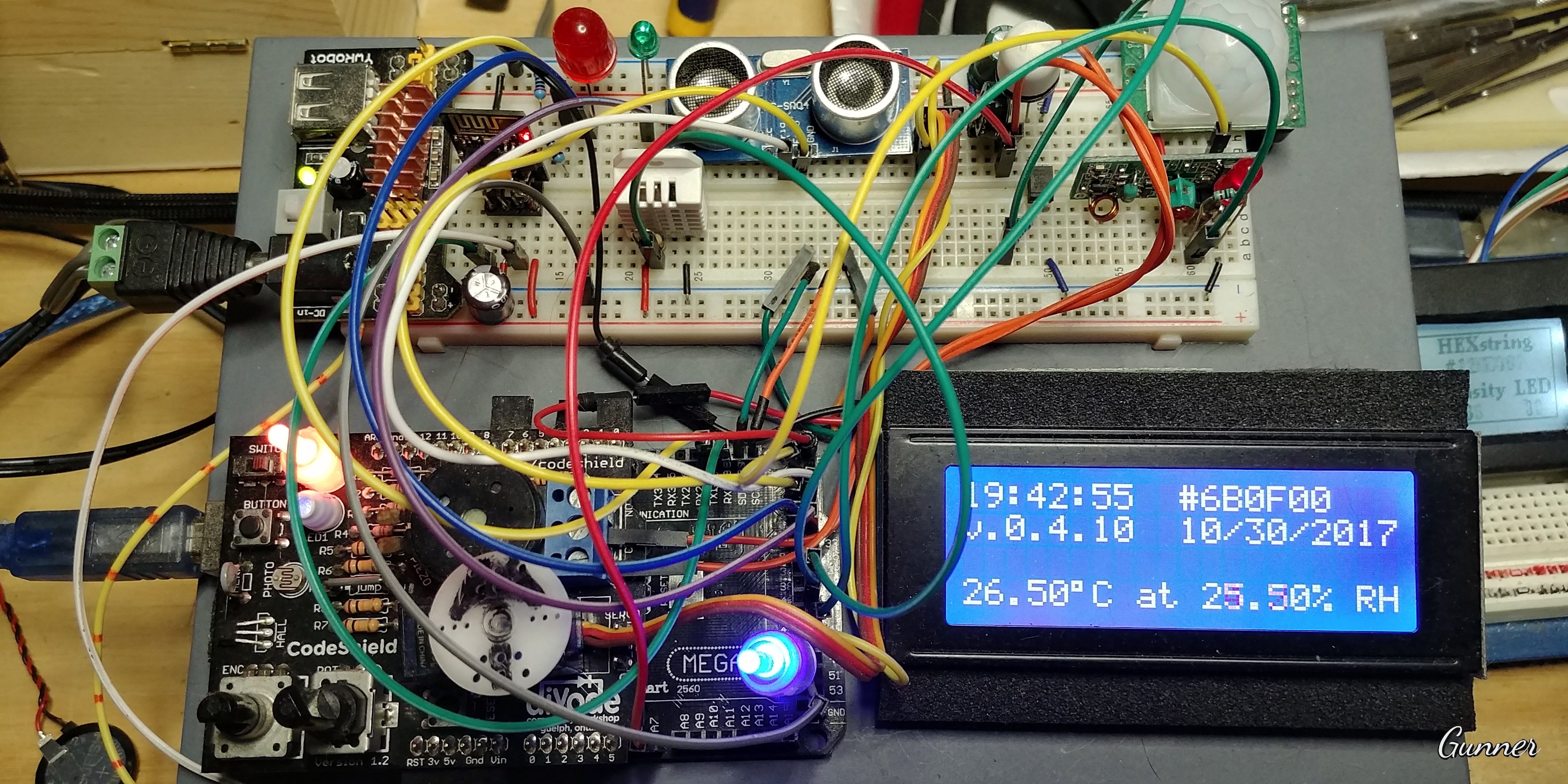
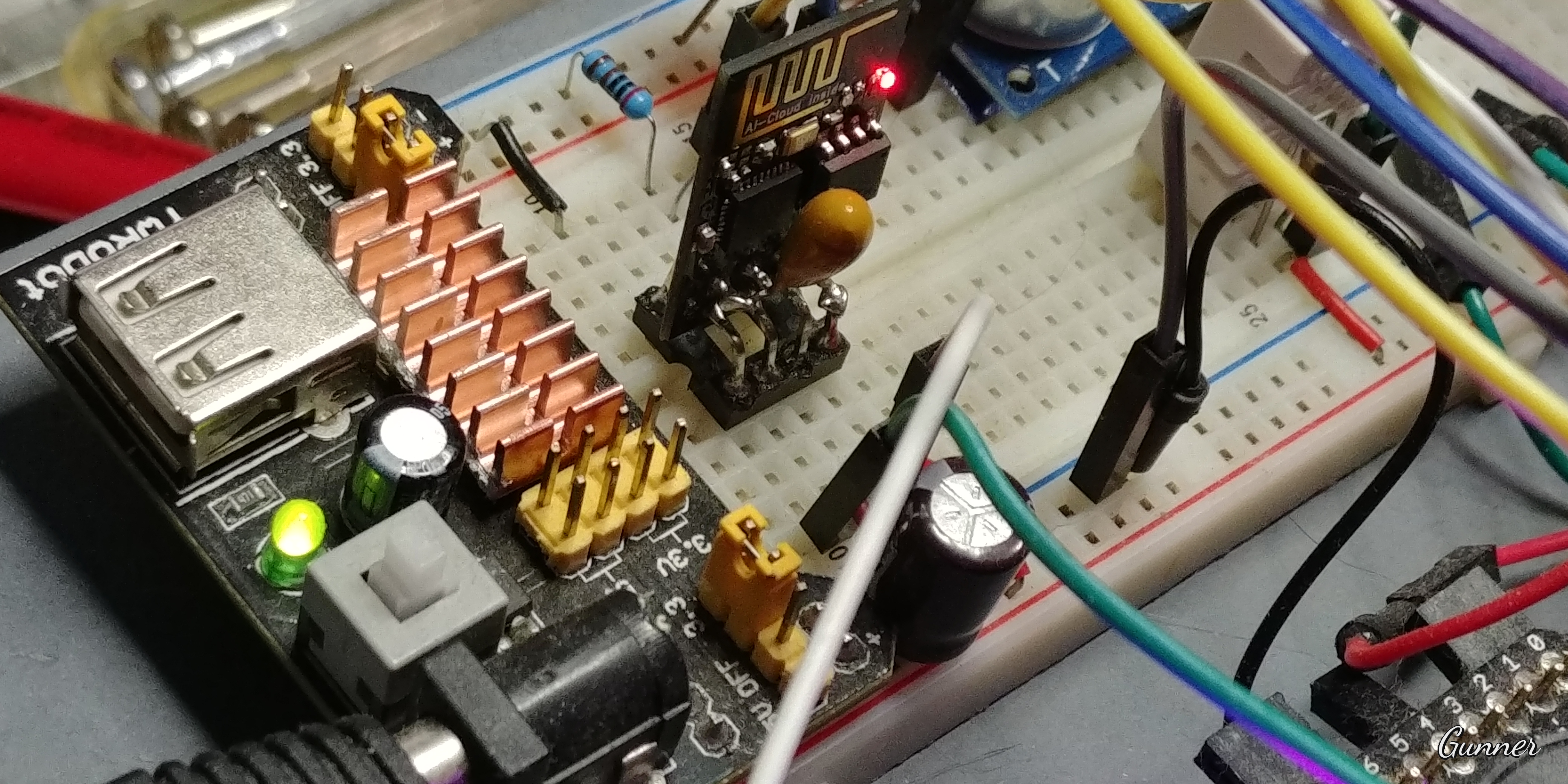
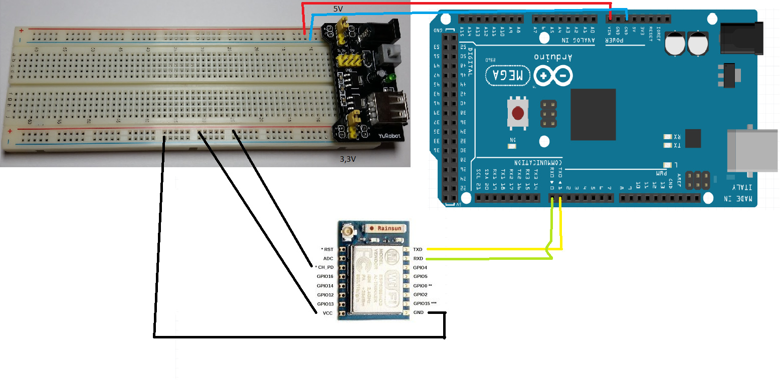
OK. First I’m use external power supply (YuRobot)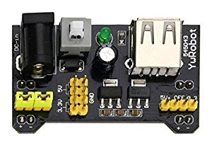
and then I’m follow this step
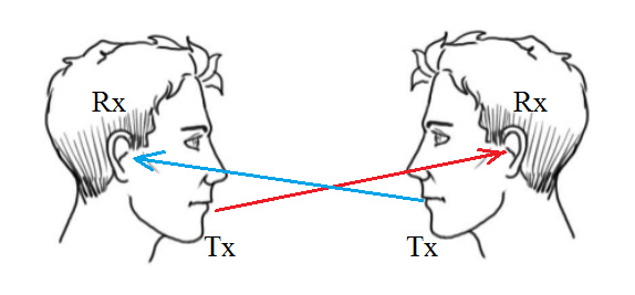
Arduino --------------------------------------------------- ESP8266
TX0->1----------------------------------------------------> TXD
RX0->0----------------------------------------------------> RXD
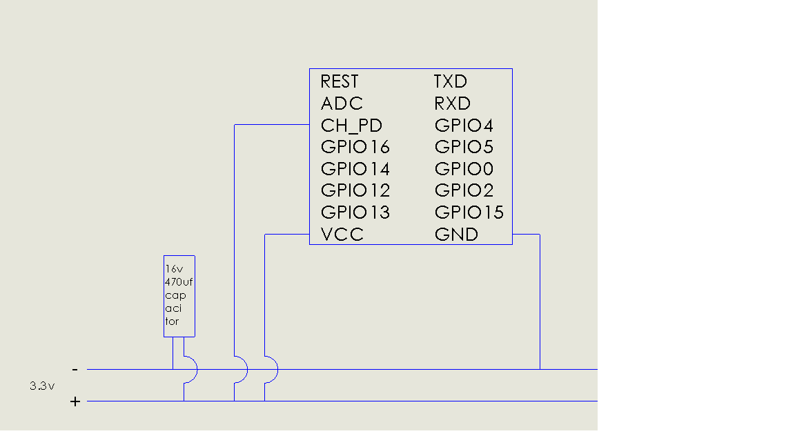
GND ----------->Power Supply<----------------------- GND
3.3 V <-----------Power Supply-----------------------> VCC
3.3 V <-----------Power Supply-----------------------> CH_PD
This is the diagram for esp8266 and arduino mega 2560 wiring
This the sketch, my inspiration from here https://www.hackster.io/TomatoMan/robot-rover-iphone-controlled-using-blynk-joystick-572153?ref=part&ref_id=15659&offset=3
#define BLYNK_PRINT Serial
#include <ESP8266_Lib.h>
#include <BlynkSimpleShieldEsp8266.h>
#include <Servo.h>

char auth[] = "TOKEN";
char ssid[] = "SSID";
char pass[] = "PASS";

#define EspSerial Serial1
#define ESP8266_BAUD 115200
ESP8266 wifi(&EspSerial);


//PIN MOTOR (USE L298N DRIVER)
int MOTOR1A = 22;
int MOTOR1B = 23;
int MOTOR2A = 24;
int MOTOR2B = 25;
int MOTOR3A = 30;
int MOTOR3B = 31;
int MOTOR4A = 32;
int MOTOR4B = 33;
int MOTOR5A = 28;
int MOTOR5B = 29;
int MOTOR6A = 26;
int MOTOR6B = 27;

//PIN MOTOR SPEED
int MOTOR1 = 7;
int MOTOR2 = 6;
int MOTOR3 = 5;
int MOTOR4 = 4;
int MOTOR5 = 3;
int MOTOR6 = 2;

//SERVO
Servo SERVO1, SERVO2, SERVO3, SERVO4, SERVO5, SERVO6;

void setup() {

//BLYNK
Serial.begin(9600);
delay(10);
EspSerial.begin(ESP8266_BAUD);
delay(10);
Blynk.begin(auth, wifi, ssid, pass);

//PIN SERVO
SERVO1.attach(13);
SERVO2.attach(12);
SERVO3.attach(11);
SERVO4.attach(10);
SERVO5.attach(9);
SERVO6.attach(8);

//SERVO BEGINING
SERVO1.write(125);
SERVO2.write(40);
SERVO3.write(35);
SERVO4.write(95);
SERVO5.write(125);
SERVO6.write(85);

//MOTOR OUTPUT
pinMode(MOTOR1A, OUTPUT);
pinMode(MOTOR1B, OUTPUT);
pinMode(MOTOR2A, OUTPUT);
pinMode(MOTOR2B, OUTPUT);
pinMode(MOTOR3A, OUTPUT);
pinMode(MOTOR3B, OUTPUT);
pinMode(MOTOR4A, OUTPUT);
pinMode(MOTOR4B, OUTPUT);
pinMode(MOTOR5A, OUTPUT);
pinMode(MOTOR5B, OUTPUT);
pinMode(MOTOR6A, OUTPUT);
pinMode(MOTOR6B, OUTPUT);

//MOTOR SPEED OUTPUT
pinMode(MOTOR1, OUTPUT);
pinMode(MOTOR2, OUTPUT);
pinMode(MOTOR3, OUTPUT);
pinMode(MOTOR4, OUTPUT);
pinMode(MOTOR5, OUTPUT);
pinMode(MOTOR6, OUTPUT);

//MOTOR BEGINING
digitalWrite(MOTOR1A, LOW);
digitalWrite(MOTOR1B, LOW);
digitalWrite(MOTOR2A, LOW);
digitalWrite(MOTOR2B, LOW);
digitalWrite(MOTOR3A, LOW);
digitalWrite(MOTOR3B, LOW);
digitalWrite(MOTOR4A, LOW);
digitalWrite(MOTOR4B, LOW);
digitalWrite(MOTOR5A, LOW);
digitalWrite(MOTOR5B, LOW);
digitalWrite(MOTOR6A, LOW);
digitalWrite(MOTOR6B, LOW);
}


void loop() {
  Blynk.run();

}

BLYNK_WRITE(V0) {

  const int X_THRESHOLD_LOW = 107; //x: 127 - 20
  const int X_THRESHOLD_HIGH = 147; //x: 127 + 20

  const int Y_THRESHOLD_LOW = 107; //y: 127 - 20
  const int Y_THRESHOLD_HIGH = 147; //y: 127 + 20

  int x_position = param[0].asInt();  //Read the Blynk Joystick x Position 0-255
  int y_position = param[1].asInt();  //Read the Blynk Joystick y Position 0-255

  int x_direction;  //Variable for Direction of Joystick Movement: x= -1, 0, 1
  int y_direction;  //Variable for Direction of Joystick Movement: y= -1, 0, 1

  Serial.print("x_position: ");
  Serial.print(x_position);
  Serial.print("  y_position: ");
  Serial.println(y_position);

//Determine the direction of the Joystick Movement
  x_direction = 0;
  y_direction = 0;

  if (x_position > X_THRESHOLD_HIGH) {
    x_direction = 1;
  } else if (x_position < X_THRESHOLD_LOW) {
    x_direction = -1;
  }
  if (y_position > Y_THRESHOLD_HIGH) {
    y_direction = 1;
  } else if (y_position < Y_THRESHOLD_LOW) {
    y_direction = -1;
  }
//if x and y are within the threshold their values then x_direction = 0 and y_direction = 0

//Move the Rover (Rover will move in the direction of the slower wheels)
//0,0(Stop); 0,1(Forward); 0,-1(Backward); 1,1(Right up diagonal); 1,0(Right); 1,-1(Right down diagonal);
//-1,0(Left); -1,1(Left up diagonal); -1,-1(Left down diagonal)

//x = -1 and y = -1 Back Diagonal Left
  if (x_direction == -1)
    if (y_direction == -1) {
        Serial.print("JOYSTICK: left-down DIRECTION: BACKWARD LEFT");
        Serial.print("  x_direction  ");
        Serial.print(x_direction);
        Serial.print("  y_direction  ");
        Serial.println(y_direction);

SERVO1.write(90);
SERVO2.write(0);
SERVO3.write(90);
SERVO4.write(95);
SERVO5.write(180);
SERVO6.write(85);
digitalWrite(MOTOR1A, LOW);
digitalWrite(MOTOR1B, HIGH);
digitalWrite(MOTOR2A, LOW);
digitalWrite(MOTOR2B, HIGH);
digitalWrite(MOTOR3A, LOW);
digitalWrite(MOTOR3B, HIGH);
digitalWrite(MOTOR4A, LOW);
digitalWrite(MOTOR4B, HIGH);
digitalWrite(MOTOR5A, LOW);
digitalWrite(MOTOR5B, HIGH);
digitalWrite(MOTOR6A, LOW);
digitalWrite(MOTOR6B, HIGH);
analogWrite(MOTOR1,127);
analogWrite(MOTOR2,255);
analogWrite(MOTOR3,127);
analogWrite(MOTOR4,127);
analogWrite(MOTOR5,255);
analogWrite(MOTOR6,255);

//x = -1 and y = 0 Left on x axis
      } else if (y_direction == 0) {
        Serial.print("JOYSTICK: left DIRECTION: TURN AROUND LEFT ");
        Serial.print("  x_direction  ");
        Serial.print(x_direction);
        Serial.print("  y_direction  ");
        Serial.println(y_direction);

SERVO1.write(35);
SERVO2.write(130);
SERVO3.write(125);
SERVO4.write(10);
SERVO5.write(35);
SERVO6.write(170);
digitalWrite(MOTOR1A, LOW);
digitalWrite(MOTOR1B, HIGH);
digitalWrite(MOTOR2A, HIGH);
digitalWrite(MOTOR2B, LOW);
digitalWrite(MOTOR3A, LOW);
digitalWrite(MOTOR3B, HIGH);
digitalWrite(MOTOR4A, LOW);
digitalWrite(MOTOR4B, HIGH);
digitalWrite(MOTOR5A, HIGH);
digitalWrite(MOTOR5B, LOW);
digitalWrite(MOTOR6A, HIGH);
digitalWrite(MOTOR6B, LOW);
analogWrite(MOTOR1,255);
analogWrite(MOTOR2,255);
analogWrite(MOTOR3,255);
analogWrite(MOTOR4,255);
analogWrite(MOTOR5,255);
analogWrite(MOTOR6,255);

//x = -1 and y = 1 Forward Diagonal Left
      } else {
        //y_direction == 1
        Serial.print("JOYSTICK left-up DIRECTION: FORWARD LEFT");
        Serial.print("  x_direction  ");
        Serial.print(x_direction);
        Serial.print("  y_direction  ");
        Serial.println(y_direction);

SERVO1.write(180);
SERVO2.write(90);
SERVO3.write(0);
SERVO4.write(95);
SERVO5.write(90);
SERVO6.write(85);
digitalWrite(MOTOR1A, HIGH);
digitalWrite(MOTOR1B, LOW);
digitalWrite(MOTOR2A, HIGH);
digitalWrite(MOTOR2B, LOW);
digitalWrite(MOTOR3A, HIGH);
digitalWrite(MOTOR3B, LOW);
digitalWrite(MOTOR4A, HIGH);
digitalWrite(MOTOR4B, LOW);
digitalWrite(MOTOR5A, HIGH);
digitalWrite(MOTOR5B, LOW);
digitalWrite(MOTOR6A, HIGH);
digitalWrite(MOTOR6B, LOW);
analogWrite(MOTOR1,127);
analogWrite(MOTOR2,255);
analogWrite(MOTOR3,127);
analogWrite(MOTOR4,127);
analogWrite(MOTOR5,255);
analogWrite(MOTOR6,255);

//x = 0 and y = -1 Backward
      } else
        if (x_direction == 0)
        if (y_direction == -1) {
        Serial.print("JOYSTICK down DIRECTION BACKWARD");
        Serial.print("  x_direction  ");
        Serial.print(x_direction);
        Serial.print("  y_direction  ");
        Serial.println(y_direction);

SERVO1.write(125);
SERVO2.write(40);
SERVO3.write(35);
SERVO4.write(95);
SERVO5.write(125);
SERVO6.write(85);
digitalWrite(MOTOR1A, LOW);
digitalWrite(MOTOR1B, HIGH);
digitalWrite(MOTOR2A, LOW);
digitalWrite(MOTOR2B, HIGH);
digitalWrite(MOTOR3A, LOW);
digitalWrite(MOTOR3B, HIGH);
digitalWrite(MOTOR4A, LOW);
digitalWrite(MOTOR4B, HIGH);
digitalWrite(MOTOR5A, LOW);
digitalWrite(MOTOR5B, HIGH);
digitalWrite(MOTOR6A, LOW);
digitalWrite(MOTOR6B, HIGH);
analogWrite(MOTOR1,255);
analogWrite(MOTOR2,255);
analogWrite(MOTOR3,255);
analogWrite(MOTOR4,255);
analogWrite(MOTOR5,255);
analogWrite(MOTOR6,255);

//x = 0 and y = 0 Stop
      } else if (y_direction == 0) {
        Serial.print("JOYSTICK: centered DIRECTION: STOP");
        Serial.print("  x_direction  ");
        Serial.print(x_direction);
        Serial.print("  y_direction  ");
        Serial.println(y_direction);

SERVO1.write(125);
SERVO2.write(40);
SERVO3.write(35);
SERVO4.write(95);
SERVO5.write(125);
SERVO6.write(85);
digitalWrite(MOTOR1A, LOW);
digitalWrite(MOTOR1B, LOW);
digitalWrite(MOTOR2A, LOW);
digitalWrite(MOTOR2B, LOW);
digitalWrite(MOTOR3A, LOW);
digitalWrite(MOTOR3B, LOW);
digitalWrite(MOTOR4A, LOW);
digitalWrite(MOTOR4B, LOW);
digitalWrite(MOTOR5A, LOW);
digitalWrite(MOTOR5B, LOW);
digitalWrite(MOTOR6A, LOW);
digitalWrite(MOTOR6B, LOW);
analogWrite(MOTOR1,0);
analogWrite(MOTOR2,0);
analogWrite(MOTOR3,0);
analogWrite(MOTOR4,0);
analogWrite(MOTOR5,0);
analogWrite(MOTOR6,0);

//x = 0 and y = 1 Forward
      } else {
        //y_direction == 1
        Serial.print("JOYSTICK: up DIRECTION: FORWARD");
        Serial.print("  x_direction  ");
        Serial.print(x_direction);
        Serial.print("  y_direction  ");
        Serial.println(y_direction);

SERVO1.write(125);
SERVO2.write(40);
SERVO3.write(35);
SERVO4.write(95);
SERVO5.write(125);
SERVO6.write(85);
digitalWrite(MOTOR1A, HIGH);
digitalWrite(MOTOR1B, LOW);
digitalWrite(MOTOR2A, HIGH);
digitalWrite(MOTOR2B, LOW);
digitalWrite(MOTOR3A, HIGH);
digitalWrite(MOTOR3B, LOW);
digitalWrite(MOTOR4A, HIGH);
digitalWrite(MOTOR4B, LOW);
digitalWrite(MOTOR5A, HIGH);
digitalWrite(MOTOR5B, LOW);
digitalWrite(MOTOR6A, HIGH);
digitalWrite(MOTOR6B, LOW);
analogWrite(MOTOR1,255);
analogWrite(MOTOR2,255);
analogWrite(MOTOR3,255);
analogWrite(MOTOR4,255);
analogWrite(MOTOR5,255);
analogWrite(MOTOR6,255);

//x = 1 and y = -1 Backward Diagonal Right
      } else
        //x_direction == 1
        if (y_direction == -1){
        Serial.print("JOYSTICK right-down DIRECTION: BACKWARD RIGHT");
        Serial.print("  x_direction  ");
        Serial.print(x_direction);
        Serial.print("  y_direction  ");
        Serial.println(y_direction);

SERVO1.write(180);
SERVO2.write(90);
SERVO3.write(0);
SERVO4.write(95);
SERVO5.write(90);
SERVO6.write(85);
digitalWrite(MOTOR1A, LOW);
digitalWrite(MOTOR1B, HIGH);
digitalWrite(MOTOR2A, LOW);
digitalWrite(MOTOR2B, HIGH);
digitalWrite(MOTOR3A, LOW);
digitalWrite(MOTOR3B, HIGH);
digitalWrite(MOTOR4A, LOW);
digitalWrite(MOTOR4B, HIGH);
digitalWrite(MOTOR5A, LOW);
digitalWrite(MOTOR5B, HIGH);
digitalWrite(MOTOR6A, LOW);
digitalWrite(MOTOR6B, HIGH);
analogWrite(MOTOR1,255);
analogWrite(MOTOR2,127);
analogWrite(MOTOR3,255);
analogWrite(MOTOR4,255);
analogWrite(MOTOR5,127);
analogWrite(MOTOR6,127);


//x = 1 and y = 0 Right on x-axis
      } else
        if (y_direction == 0){
        Serial.print("JOYSITCK: right DIRECTION: TURN AROUND RIGHT");
        Serial.print("  x_direction  ");
        Serial.print(x_direction);
        Serial.print("  y_direction  ");
        Serial.println(y_direction);

SERVO1.write(35);
SERVO2.write(130);
SERVO3.write(125);
SERVO4.write(10);
SERVO5.write(35);
SERVO6.write(170);
digitalWrite(MOTOR1A, HIGH);
digitalWrite(MOTOR1B, LOW);
digitalWrite(MOTOR2A, LOW);
digitalWrite(MOTOR2B, HIGH);
digitalWrite(MOTOR3A, HIGH);
digitalWrite(MOTOR3B, LOW);
digitalWrite(MOTOR4A, HIGH);
digitalWrite(MOTOR4B, LOW);
digitalWrite(MOTOR5A, LOW);
digitalWrite(MOTOR5B, HIGH);
digitalWrite(MOTOR6A, LOW);
digitalWrite(MOTOR6B, HIGH);
analogWrite(MOTOR1,255);
analogWrite(MOTOR2,255);
analogWrite(MOTOR3,255);
analogWrite(MOTOR4,255);
analogWrite(MOTOR5,255);
analogWrite(MOTOR6,255);

//x = 1 and y = 1 Forward Diagonal Right
      } else {
        //y_direction == 1
        Serial.print("JOYSTICK: right-up DIRECTION: RIGHT");
        Serial.print("  x_direction  ");
        Serial.print(x_direction);
        Serial.print("  y_direction  ");
        Serial.println(y_direction);

SERVO1.write(90);
SERVO2.write(0);
SERVO3.write(90);
SERVO4.write(95);
SERVO5.write(180);
SERVO6.write(85);
digitalWrite(MOTOR1A, HIGH);
digitalWrite(MOTOR1B, LOW);
digitalWrite(MOTOR2A, HIGH);
digitalWrite(MOTOR2B, LOW);
digitalWrite(MOTOR3A, HIGH);
digitalWrite(MOTOR3B, LOW);
digitalWrite(MOTOR4A, HIGH);
digitalWrite(MOTOR4B, LOW);
digitalWrite(MOTOR5A, HIGH);
digitalWrite(MOTOR5B, LOW);
digitalWrite(MOTOR6A, HIGH);
digitalWrite(MOTOR6B, LOW);
analogWrite(MOTOR1,255);
analogWrite(MOTOR2,127);
analogWrite(MOTOR3,255);
analogWrite(MOTOR4,255);
analogWrite(MOTOR5,127);
analogWrite(MOTOR6,127);

      }
  }
This information enough? Did I miss something?
 switch your ESP to pins 18(TX1) & 19(RX1) and use Serial1 instead for connection.