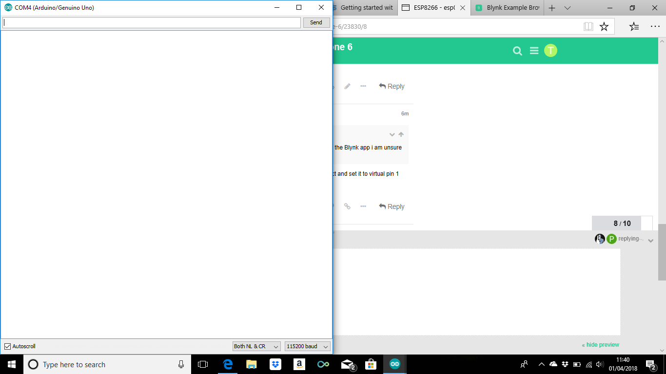
I am just trying to control a LED from a digital output using an ESP8266- 01 module. So far i have followed a very good tutorial from Jaycon systems (https://www.jayconsystems.com/tutorials/esp01). I have managed to complete everything until you get to the mobile app (as i do not have a android phone i cannot complete it).So, i am happy that the WIFI module will transmit atleast. Next i downloaded the example on BLYNK to turn the LED on and off but i am getting a little confused. Do i have to change the board on the Arduino program to ESP8266 generic? i have tried this but i keep getting an error message. I tried it on the Arduino uno board which doesn’t get any error messages but on the Blynk app i am unsure it is connecting. Can anyone help?
/* Comment this out to disable prints and save space */
#define BLYNK_PRINT Serial
#include <ESP8266_Lib.h>
#include <BlynkSimpleShieldEsp8266.h>
// You should get Auth Token in the Blynk App.
// Go to the Project Settings (nut icon).
char auth[] = "1b93b8d0f3584d2e93103ed8f02ece33";
// Your WiFi credentials.
// Set password to "" for open networks.
char ssid[] = "VM0046337";
char pass[] = "txY445cd8gews";
// or Software Serial on Uno, Nano...
#include <SoftwareSerial.h>
SoftwareSerial EspSerial(2, 3); // RX, TX
// Your ESP8266 baud rate:
#define ESP8266_BAUD 115200
ESP8266 wifi(&EspSerial);
WidgetLED led1(V1);
BlynkTimer timer;
// V1 LED Widget is blinking
void blinkLedWidget()
{
if (led1.getValue()) {
led1.off();
Serial.println("LED on V1: off");
} else {
led1.on();
Serial.println("LED on V1: on");
}
}
void setup()
{
// Debug console
Serial.begin(9600);
// Set ESP8266 baud rate
EspSerial.begin(ESP8266_BAUD);
delay(10);
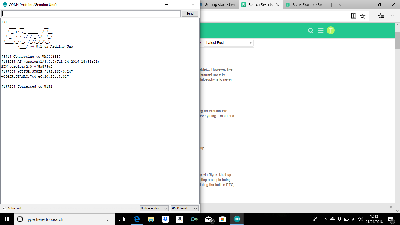
Blynk.begin(auth, wifi, ssid, pass);
// You can also specify server:
//Blynk.begin(auth, wifi, ssid, pass, "blynk-cloud.com", 8442);
//Blynk.begin(auth, wifi, ssid, pass, IPAddress(192,168,1,100), 8442);
timer.setInterval(1000L, blinkLedWidget);
}
void loop()
{
Blynk.run();
timer.run();
}```
Once you have a better grasp you will be able to know what questions you still need to ask.
You can use the ESP-01 in standalone or as a WiFi shield for the UNO… The most common is the latter…in which case you program the UNO as an UNO… the ESP is just a Serial to WiFi adapter.
Why are you using the Arduino UNO?
The ESP8266 has more processing power, more memory and has built-in Wi-Fi. It can be programmed directly using the Arduino IDE (once you’ve installed the ESP8266 core).
To be honest all i have is a ESP8266 01 module and a Arduino Uno. I am powering the ESP8266 through the Arduino and i have assumed i have to connect the TX and RX to the Arduino. Ultimately, what i would like to do for a College project is see if a power source is on and then control from a distance (not as close as Bluetooth). So, for example i could see if i have left the iron on while I’m down the pub then turn it off using my phone. Before i get to that stage i just wanted to get a basic understanding on what i am doing (i am pretty new at this) so i thought i would maybe just control and LED through my phone to start. Am i going about this the wrong way do you think ?
With the example you loaded… you need to put a LED widget into your App project and set it to virtual pin 1 (V1)… it should then start “blinking” when you start the project.
Some think new users should only use full ESP development boards (built in USB and lots of pins)… mainly because they are “easier” to learn (debatable)…
However, like you, I started out with none of that (didn’t even have an ESP-01) and found that I learned more by working with what I had, and slowly growing into the newer, bigger, better… My philosophy is to never let someone else tell me not to do something that I can learn from… Basically though it is a personal preference and your choice
To control a virtual LED he doesn’t even need one of those GPIOs
Even for controlling a relay, plus a physical button to turn the relay on and off without the app, he’s still only using two out of the three GPIO pins, so he could use the third for a physical LED as well.
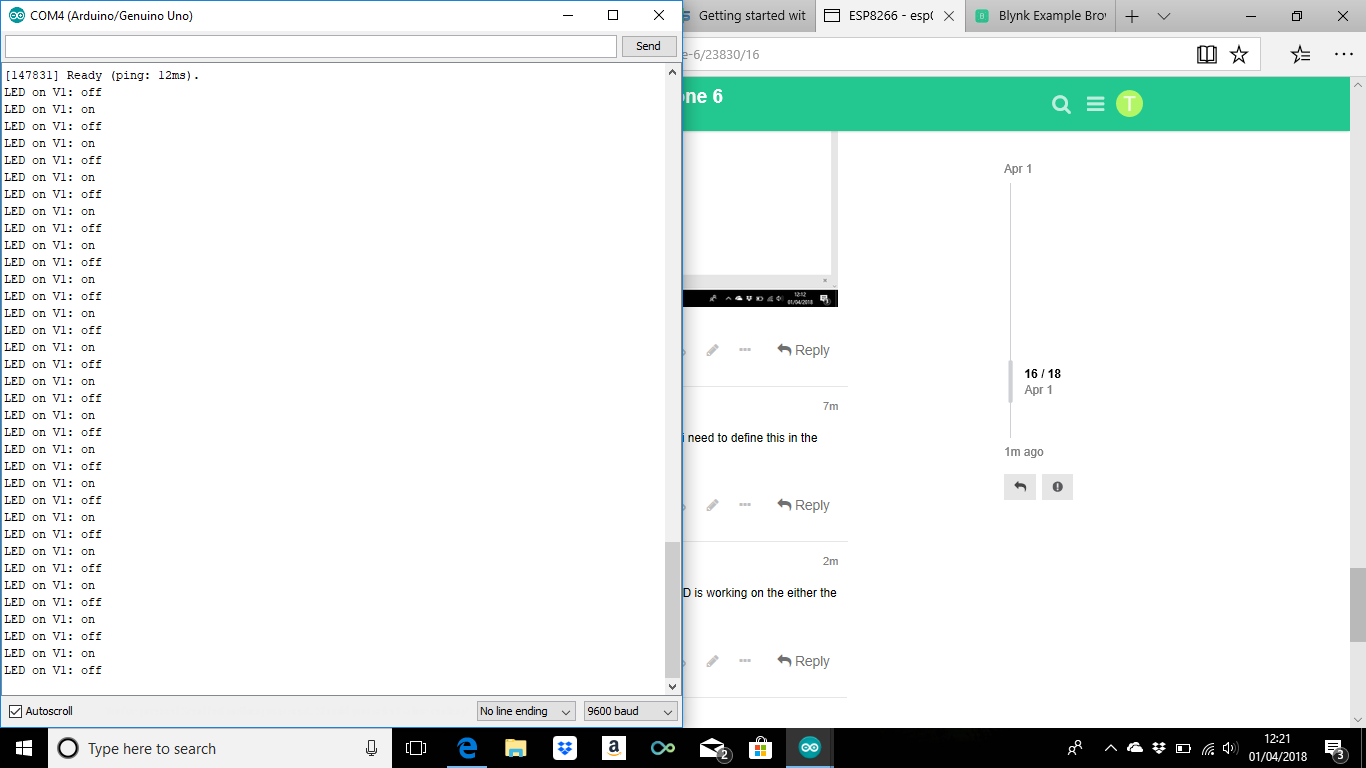
scrap that, i am connected on the app and the LED is alight on the app. But no LED is working on the either the ESP8266 and i cannot turn it on or off on the app
The only LED that should show on the ESP is the power (if it has one) and the transmit (or receive… can’t remember which) and even that may not show depending on the manufacture.
But the serial monitor output is correct and you should see the virtual LED (on V1) in the App 'blinking" the same way.