ESP8266 and LED display do not communicate

Hi,

Getting started with Arduino and Blynk. Made the first “blink LED” projects with and without Blynk, worked as should. Now would like to go on and try to connect a 4-digit 7-segment display (TM1637) to the Arduino board (NodeMCU). Have all the needed libraries, but nothing happens if the code (simple test example) is uploaded. Same code works on Arduino UNO, but not with NodeMCU (testedV1.0 and V3.0 boards). Tried different pins, but still nothing. Any ideas what to check?

EDIT: Solved!
If You have problems with this set
If CLK is connected to D6 and DIO is connected to D5, exactly as written on board.
#define CLK D6
#define DIO D5

Are you using the correct pins? The D numbers printed on the NodeMCU boards aren’t GPIO numbers. You need to check a pinout diagram for your board to translate these to GPIOs.

If that isn’t the issue then you need to provide more info - code (correctly formatted), wiring diagram, serial monitor output etc.

Pete.

This is totally new information for me :thinking: . Worked fine if used for command “blink LED”.

will check!!
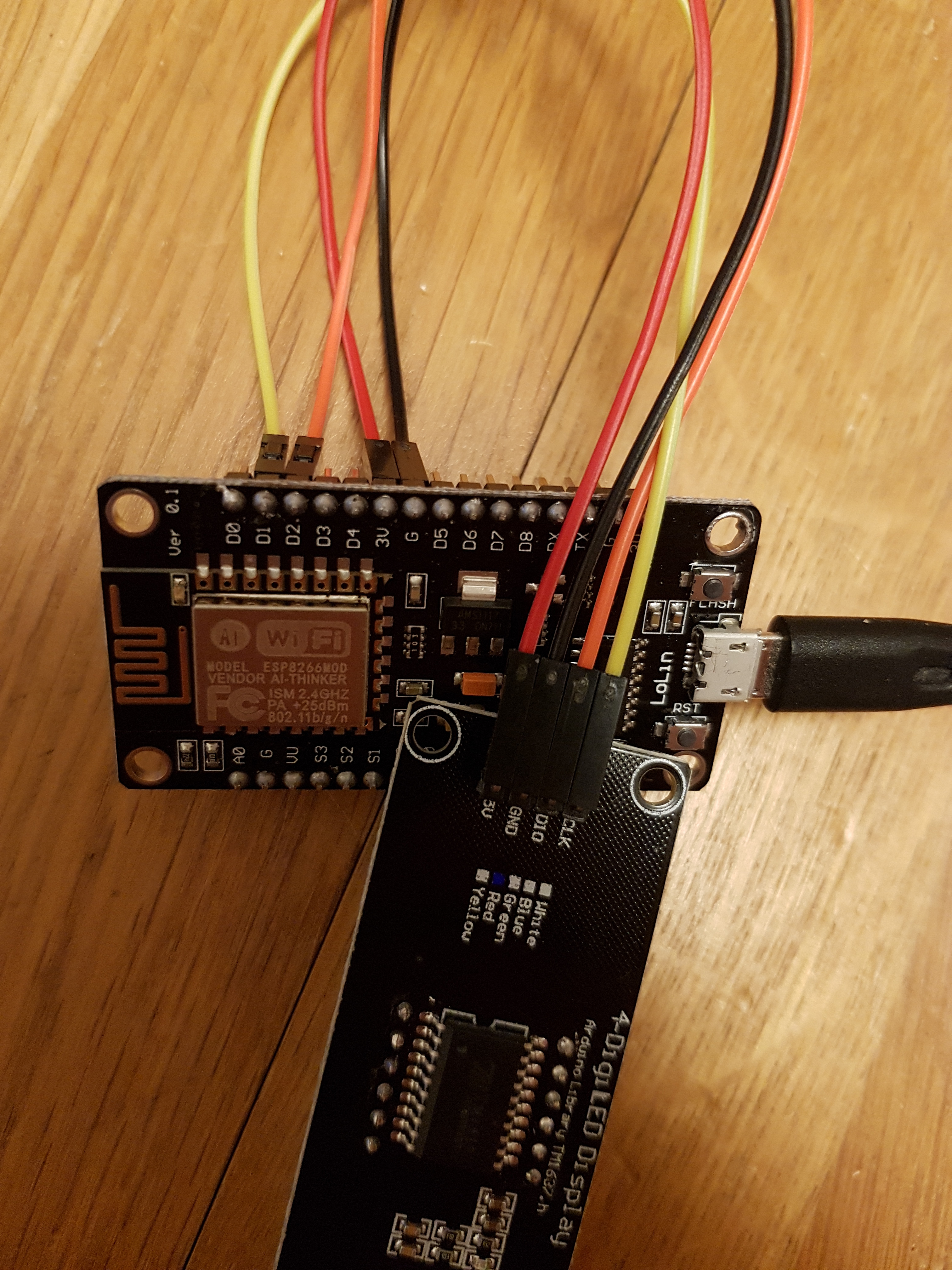
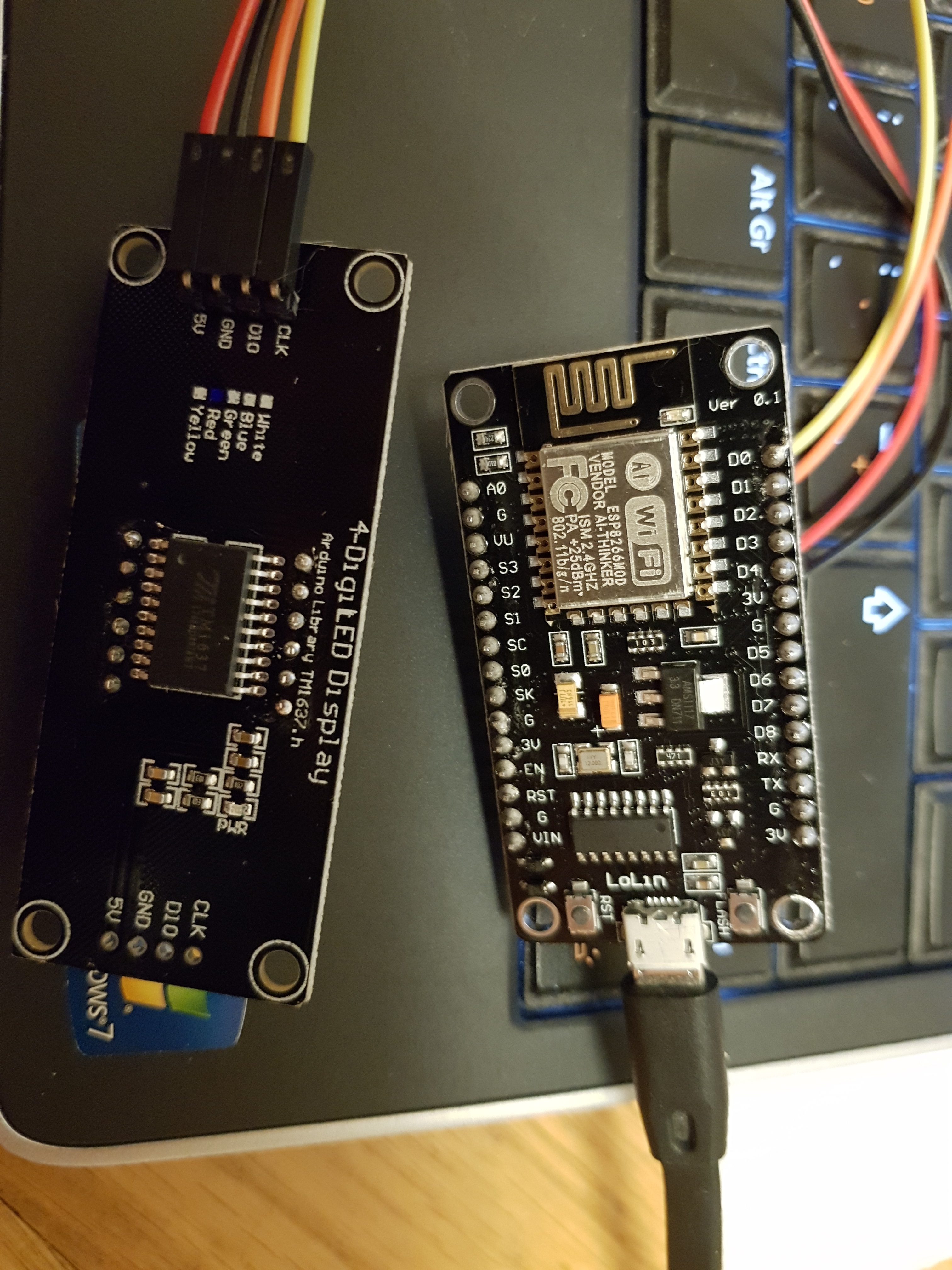
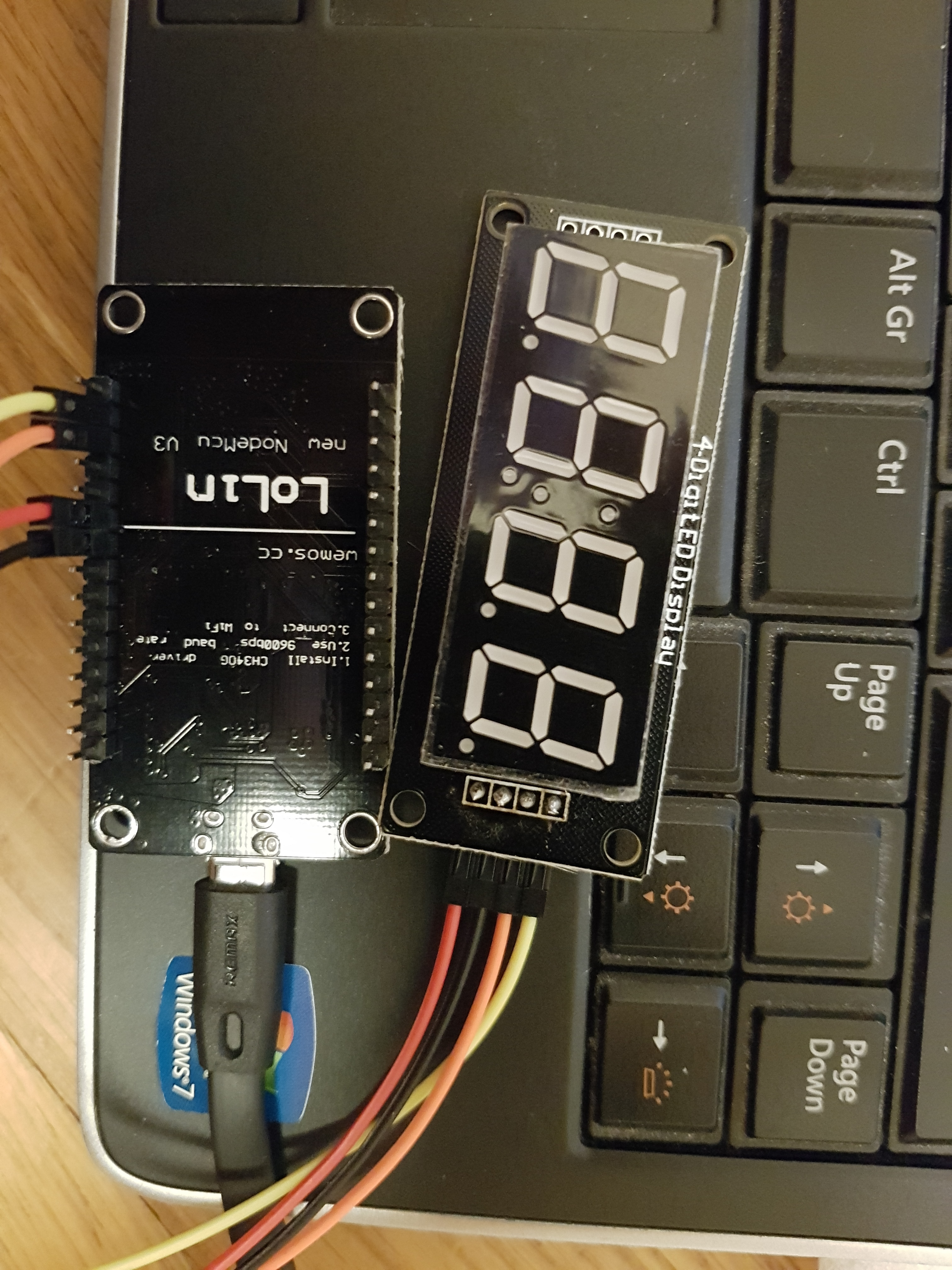
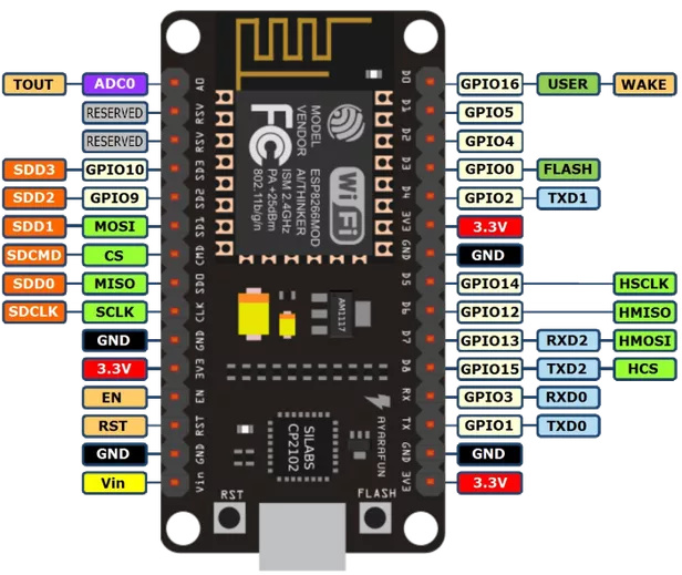
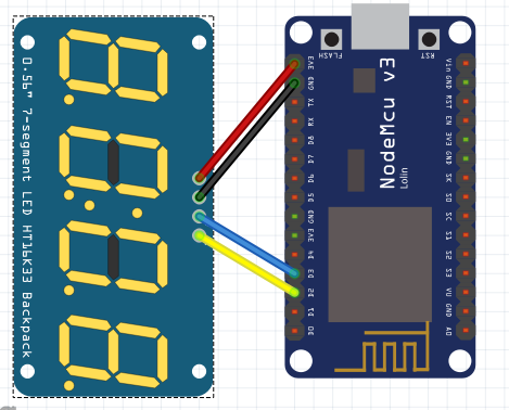
what pins to used based on this picture:


connection schematic is in next post, new user can not post 2 pictures in 1 post :grinning:
Test CODE:

#include <Arduino.h>
#include <TM1637Display.h>

// Module connection pins (Digital Pins)
#define CLK 2
#define DIO 3

// The amount of time (in milliseconds) between tests
#define TEST_DELAY   2000

const uint8_t SEG_DONE[] = {
	SEG_B | SEG_C | SEG_D | SEG_E | SEG_G,           // d
	SEG_A | SEG_B | SEG_C | SEG_D | SEG_E | SEG_F,   // O
	SEG_C | SEG_E | SEG_G,                           // n
	SEG_A | SEG_D | SEG_E | SEG_F | SEG_G            // E
	};

TM1637Display display(CLK, DIO);

void setup()
{
}

void loop()
{
  int k;
  uint8_t data[] = { 0xff, 0xff, 0xff, 0xff };
  display.setBrightness(0x0f);

  // All segments on
  display.setSegments(data);
  delay(TEST_DELAY);

  // Selectively set different digits
  data[0] = 0b01001001;
  data[1] = display.encodeDigit(1);
  data[2] = display.encodeDigit(2);
  data[3] = display.encodeDigit(3);

  for(k = 3; k >= 0; k--) {
	display.setSegments(data, 1, k);
	delay(TEST_DELAY);
	}

  display.setSegments(data+2, 2, 2);
  delay(TEST_DELAY);

  display.setSegments(data+2, 2, 1);
  delay(TEST_DELAY);

  display.setSegments(data+1, 3, 1);
  delay(TEST_DELAY);


  // Show decimal numbers with/without leading zeros
  bool lz = false;
  for (uint8_t z = 0; z < 2; z++) {
	for(k = 0; k < 10000; k += k*4 + 7) {
		display.showNumberDec(k, lz);
		delay(TEST_DELAY);
	}
	lz = true;
  }

  // Show decimal number whose length is smaller than 4
  for(k = 0; k < 4; k++)
	data[k] = 0;
  display.setSegments(data);

	// Run through all the dots
	for(k=0; k <= 4; k++) {
		display.showNumberDecEx(0, (0x80 >> k), true);
		delay(TEST_DELAY);
	}

  display.showNumberDec(153, false, 3, 1);
  delay(TEST_DELAY);
  display.showNumberDec(22, false, 2, 2);
  delay(TEST_DELAY);
  display.showNumberDec(0, true, 1, 3);
  delay(TEST_DELAY);
  display.showNumberDec(0, true, 1, 2);
  delay(TEST_DELAY);
  display.showNumberDec(0, true, 1, 1);
  delay(TEST_DELAY);
  display.showNumberDec(0, true, 1, 0);
  delay(TEST_DELAY);

  // Brightness Test
  for(k = 0; k < 4; k++)
	data[k] = 0xff;
  for(k = 0; k < 7; k++) {
    display.setBrightness(k);
    display.setSegments(data);
    delay(TEST_DELAY);
  }
  
  // On/Off test
  for(k = 0; k < 4; k++) {
    display.setBrightness(7, false);  // Turn off
    display.setSegments(data);
    delay(TEST_DELAY);
    display.setBrightness(7, true); // Turn on
    display.setSegments(data);
    delay(TEST_DELAY);  
  }

  // Done!
  display.setSegments(SEG_DONE);

  while(1);
}

image

This says that you’re using GPIO2 and GPIO3 as your data connections to your display.
Your diagram shows that you’ve used D2 (GPIO4) and D3 (GPIO0).

You could either keep the code the same and move the connections to D4 (GPIO2) and RX (GPIO3) or alternatively keep the connections the same and change the code to:
#define CLK 4
#define DIO 0

BUT, using RX as a data pin isn’t the best idea, and using GPIO0 (D3) isn’t great either.

I’d surest you connect your dlisplay to GPIO5 (D1) and GPIO4 (D2) and change your code to:
#define CLK 5
#define DIO 4

Hope this makes sense!

You’ll find that a printout of those NodeMCU pinouts becomes your new best friend for a while.
The Arduino IDE does allow you to reference the D pins directly (#define CLK D1 for example), but this is sloppy programming practice as it makes translation of code between devices more difficult.

Pete.

1 Like

Wow!

This kind of support is that drives the motivation to continue, and hope I can also help someone one fine day.

Thank You!

You’re welcome.
If you now have the display working, you should take a look at restructuring your code so that you take all of that stuff out of your void loop before Blynkifying your code.

You should also mark the topic as Solved.

Pete.

I market the topic solved before actually testing it out, i was travelling before :confused:.

Today had time to test it, and it still does not work. Changed the pins as reccomended on board and code. Double checked board and GPIO chart. After upload nothing happens :sweat_smile:.

Can I measure some voltage from pins? Probably not, as it is data.

So what should your current code and connection setup?
Can you post a photo of the actual setup, not a wiring diagram, as there’s a possibility that the two could accidentally be different.

Pete.

Be aware, that TM1637 is a 5V logic device. I’m not telling You it won’t work under 3,3V, but I’m telling it is out of specs:

Tested also VU pin with red wire (VU is/should be 5V directly from usb)

Still 0,7*5V = 3,5V > 3,3V

If the above not working, then it may need level conversion to work…

Good catch @marvin7
@une18 the device certainly needs 5v to power it, but it appears that it should also be receiving 5v logic level signals on the CLK and DIO pins, but the NodeMCU works on 3.3v logic levels.

You could potentially try a logic level converter (I’ve never had much joy with these personally) or voltage divider to change the logic levels to 5v.

Pete.

This got now more complicated…

Did set on VU
Measured voltage between pins 5.0V G and VU
4.96 CLK and G constant
4.96 DIO and G constant

Then I must warn you, that ESP is not 5V tolerant (although at least one on the world is - mine survived, when unintentionally connected to 5V)

But multimeter is not enough. At least some logic analyzer or scope. Or even some LED interface, where You will be able to observe short pulses… Multimeter on voltage measurement mode is just too slow.

Guys… at risk of repetitious repeating of repeatable statements… this is NOT a Blynk related issue… at least not yet, maybe after it works with basic code…

For example…

1 Like

I am new here! It is not ok to ask help from other Blynk users? I thought all skill level Blynk users can ask/give support.

But you haven’t asked a single Blynk related question yet :stuck_out_tongue_winking_eye: And in a few seconds I found the answers (on Google) to the questions that you did ask :wink:

As has been repeatedly referenced in this forum… just becasue one uses the word Blynk in their vocabulary… doesn’t mean instant solutions in a Blynk forum for non-Blynk issues… particularly when it is the FIRST request.

Yes, many established Blynk projects get more non-Blynk related attention and assistance becasue, well, there is actual Blynk relevance in them.

Once you have it physically/mechanically/electrically functional… then please continue on with making it work with Blynk commands… and on that we can most assuredly assist.

.