ESP32 with Blynk 2.0 facing problem to drive high power 3W led in parallel

Hi,

I am new to Blynk & ESP32 programming. I used google to complete a custom code to drive an aquarium light with 8 different led channel & PWM control. (For better understanding, I am adding the code after the post).

List of hardware used,

  1. 5V - 30A Power supply
  2. irfz44n N-Chn Mosfet (9 pcs)
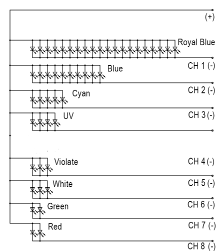
  3. High Power 3W SMD LED (20 Royal Blue, 10 Blue, 5 Cyan, 2 green, 3 white, 5 UV, 3 Purple, 2 Red)
  4. 2 pcs 5V Cooling fan
  5. ESP32 Espressif board
  6. Logic level converter

What I did to complete the circuit.

  • For Royal Blue Channel:
  • ESP32 (GPIO 13) to Logiclevel converter to make the signal 3.3V to 5V.
  • Logic level converter to Mosfet Gate
  • Mosfet source to power supply Ground (-)
  • Mosfet drain to 20 pcs 3w LED in parallel.
  • Same goes to all other color of LED’s

Note: I did not used any resistor or any other parts that are not mentioned in the post.

Problems:

  1. When i turn on a channel, the LED’s are not in full brightness.
  2. Small LED flickering can be noticed in naked eye (8bit, 3000 HZ)
  3. The LED’s turns off after few minutes when the load becomes high or when 2-3 channel of LED turned on at the same time.

Main Problem: LED’s are not at the full brightness. How can I achieve full brightness of the LED’s.

** For blynk datastream I used 0-160. As 160 provides me with 3.6V measured with multi tester. After getting dimmed LED, I changed the maximum to 255. Still same result.**

Your help will be highly appriciated.

   #define APP_DEBUG

   // Uncomment your board, or configure a custom board in Settings.h
   //#define USE_WROVER_BOARD
   //#define USE_TTGO_T7
   //#define USE_ESP32C3_DEV_MODULE
   //#define USE_ESP32S2_DEV_KIT

   #include "BlynkEdgent.h"

   int ledPin1 = 16; //White "RX2"
   int ledPin2 = 13; //Royal Blue "D13"
   int ledPin3 = 18; //Blue "D18"
   int ledPin4 = 19; //Purple D19
   int ledPin5 = 32; //UV "D32" 
   int ledPin6 = 21; //Cyan "D21"
   int ledPin7 = 22; //Green "D22"
   int ledPin8 = 23; //Red "D23"
   int ledPin9 = 26; //Master "D26"
   int ledPin10 = 25; //Fan "D25"

   int button_v9_value;
   int pinValue1; //White
   int pinValue2; //Royal Blue
   int pinValue3; //Blue
   int pinValue4; //Purple
   int pinValue5; //UV
   int pinValue6; //Cyan
   int pinValue7; //Green
   int pinValue8; //Red
   int pinValue9; //Master
   int pinValue10; //Fan

   const int chn1 = 0; //White
   const int chn2 = 1; //Royal Blue
   const int chn3 = 2; //Blue
   const int chn4 = 3; //Purple
   const int chn5 = 4; //UV
   const int chn6 = 5; //Cyan
   const int chn7 = 6; //Green
   const int chn8 = 7; //Red
   const int chn9 = 8; //Master
   const int chn10 = 9; //Fan
      
   const int frq = 3000;
   const int res = 8;


   BLYNK_CONNECTED()
   {
     Blynk.syncAll();
   }


   BLYNK_WRITE(V0)
   {
     pinValue1 = param.asInt(); // assigning incoming value from pin V1 to a variable
     if (button_v9_value == 1)
     {
     ledcWrite(chn1, pinValue1);
     Serial.print("V0 Slider value is: ");
     Serial.println(pinValue1);
     delay(30);
     }
   }

   BLYNK_WRITE(V1)
   {
     pinValue2 = param.asInt(); // assigning incoming value from pin V1 to a variable
     if (button_v9_value == 1)
     {
     ledcWrite(chn2, pinValue2);
     Serial.print("V1 Slider value is: ");
     Serial.println(pinValue2);
     delay(30);
     }
   }

   BLYNK_WRITE(V2)
   {
     pinValue3 = param.asInt(); // assigning incoming value from pin V1 to a variable
     if (button_v9_value == 1)
     {
     ledcWrite(chn3, pinValue3);
     Serial.print("V2 Slider value is: ");
     Serial.println(pinValue3);
     delay(30);
     }
   }

   BLYNK_WRITE(V3)
   {
     pinValue4 = param.asInt(); // assigning incoming value from pin V1 to a variable
     if (button_v9_value == 1)
     {
     ledcWrite(chn4, pinValue4);
     Serial.print("V3 Slider value is: ");
     Serial.println(pinValue4);
     delay(30);
     }
   }

   BLYNK_WRITE(V4)
   {
     pinValue5 = param.asInt(); // assigning incoming value from pin V1 to a variable
     if (button_v9_value == 1)
     {
     ledcWrite(chn5, pinValue5);
     Serial.print("V4 Slider value is: ");
     Serial.println(pinValue5);
     delay(30);
     }
   }

   BLYNK_WRITE(V5)
   {
     pinValue6 = param.asInt(); // assigning incoming value from pin V1 to a variable
     if (button_v9_value == 1)
     {
     ledcWrite(chn6, pinValue6);
     Serial.print("V5 Slider value is: ");
     Serial.println(pinValue6);
     delay(30);
     }
   }

   BLYNK_WRITE(V6)
   {
     pinValue7 = param.asInt(); // assigning incoming value from pin V1 to a variable
     if (button_v9_value == 1)
     {
     ledcWrite(chn7, pinValue7);
     Serial.print("V6 Slider value is: ");
     Serial.println(pinValue7);
     delay(30);
     }
   }

   BLYNK_WRITE(V7)
   {
     pinValue8 = param.asInt(); // assigning incoming value from pin V1 to a variable
     if (button_v9_value == 1)
     {
     ledcWrite(chn8, pinValue8);
     Serial.print("V7 Slider value is: ");
     Serial.println(pinValue8);
     delay(30);
     }
   }

   BLYNK_WRITE(V8)
   {
     pinValue9 = param.asInt(); // assigning incoming value from pin V1 to a variable
     if (button_v9_value == 1)
     {
     ledcWrite(chn9, pinValue9);
     Serial.print("V8 Slider value is: ");
     Serial.println(pinValue9);
     delay(30);
     }
   }

   BLYNK_WRITE(V10)
   {
     pinValue10 = param.asInt(); // assigning incoming value from pin V1 to a variable
     if (button_v9_value == 1)
     {
     ledcWrite(chn10, pinValue10);
     Serial.print("V10 Slider value is: ");
     Serial.println(pinValue10);
     delay(30);
     }
   }


   BLYNK_WRITE(V9)
   // This function is triggered when the widget attached to V9 changes in the app
   {
     button_v9_value = param.asInt(); // get the value of the button widget and store
     
     if(button_v9_value == 0)
       {
         ledcWrite(chn1,0);
         ledcWrite(chn2,0);
         ledcWrite(chn3,0);
         ledcWrite(chn4,0);
         ledcWrite(chn5,0);
         ledcWrite(chn6,0);
         ledcWrite(chn7,0);
         ledcWrite(chn8,0);
         ledcWrite(chn9,0);
         ledcWrite(chn10,0);
       }
     else
       {
         ledcWrite(chn1, pinValue1);
         ledcWrite(chn2, pinValue2);
         ledcWrite(chn3, pinValue3);
         ledcWrite(chn4, pinValue4);
         ledcWrite(chn5, pinValue5);
         ledcWrite(chn6, pinValue6);
         ledcWrite(chn7, pinValue7);
         ledcWrite(chn8, pinValue8);
         ledcWrite(chn9, pinValue9);
         ledcWrite(chn10, pinValue10);
       }
   }

   void setup()
   {
     ledcSetup(chn1,frq,res);
     ledcSetup(chn2,frq,res);
     ledcSetup(chn3,frq,res);
     ledcSetup(chn4,frq,res);
     ledcSetup(chn5,frq,res);
     ledcSetup(chn6,frq,res);
     ledcSetup(chn7,frq,res);
     ledcSetup(chn8,frq,res);
     ledcSetup(chn9,frq,res);
     ledcSetup(chn10,frq,res);
     
     ledcAttachPin(ledPin1,chn1);
     ledcAttachPin(ledPin2,chn2);
     ledcAttachPin(ledPin3,chn3);
     ledcAttachPin(ledPin4,chn4);
     ledcAttachPin(ledPin5,chn5);
     ledcAttachPin(ledPin6,chn6);
     ledcAttachPin(ledPin7,chn7);
     ledcAttachPin(ledPin8,chn8);
     ledcAttachPin(ledPin9,chn9);
     ledcAttachPin(ledPin10,chn10);
     
     Serial.begin(115200);
     delay(100);

     BlynkEdgent.begin();
   }

   void loop() {
     BlynkEdgent.run();
   }

@Saimoon24 Please edit your post, using the pencil icon at the bottom, and add triple backticks at the beginning and end of your code so that it displays correctly.
Triple backticks look like this:
```

Copy and paste these if you can’t find the correct symbol on your keyboard.

I’d also suggest providing details of how you’ve configured the datastreams, especially the min/max values for the slider datastreams.

Pete.

Dear Pete,

Thanks for the suggestion. I edited the post as you mentioned.
For datastreams I used Min 0 - Max 160 to get 3.6V maximum
Later tried Min 0 - Max 255 to get higher brightness, still no change.

Thank You.

I’d always suggest that you un-comment one of the board types and check that you are aware which pins are being used by Edgent in Settings.h, and probably add those to this list as comments so that you can see your pin usage in one place…

More info on that here…

You won’t get full brightness unless you use 255 as your maximum with 8 bit resolution. Also, it’s duty cycle not voltage that you’re measuring, so unless you have an oscilloscope available you won’t be able to take any sensible measurements.

I’m not clear why the logic level converter is required, what the specification of your LEDs are. Generally speaking, you would design your circuit so that you feed your MOSFETs with the desired output voltage for the LEDs, then drive the MOSFETs so that the full voltage is delivered when the maximum duty cycle is applied.
Your flickering is probably also caused by your circuit design.

Pete.

Thanks Pete for the suggestions. I tried with 255 too. Still same result.
I used logic level converter, as IRFZ44N mosfet’s threshold voltage is 2V where it can deliver only 1A if applied 2V to the gate. My ESP can deliver a maximum of 3.3V to the Mosfet’s gate. To get 15A out of the Mosfet’s, I had to provide at least 5V to the gate. That’s why i use logic level converter to increse 3.3V to 5V signal.

Each LED specification:
Maximum Voltage: 3.6 V
Current reuired: 600-800mA

To run 20 pcs led connected in parallel, I need 3.6V 12-16A of current.

As my power supply provides 5V voltage, I tried to lower the duty cycle to supply 3.6V through the Drain of the mosfet.

If I disconnect everything and try to turn on the led’s of each color with a different power supply(3.4V 5A) all the led’s lights up at full brightness without any issue. That means, I have no connection problem in parallel LED’s.

For assuring my connection, please see below,

Mosfet’s “Source leg” (Right most pin) : connected to the negative of My main power supply (5V 40A)

Mosfet’s “Gate Leg” (Left most pin) : connected to the ESP GPIO pin through logic level converter.

MOSFET’S “Drain leg” (Middle pin) : connected to the parallel led’s Negative wire.

Positive wire of my power supply is connected directly to the positive wire of my LED’s.

Correct me if anythibg wrong in above.

Thanks

And that’s where you’re going wrong. As I explained earlier, you need to reduce the supply voltage to the MOSFETs and run them at 100% duty cycle if you want full brightness.

Pete.

Ok, Will try that tomorrow and let you know, Thanks.

Hello Pete,

Sorryfor my late response. I was busy for few days, so couldn’t try the project. I tried to run the project with 3.5V 22A power supply today.

  • First, I tried to run each color parallel led directly from the pwer supply. It took 1.58A for blue, 1A for white, .85A for cyan. Etc. (They were lighting up fine except Royal blue color. As royal blue has 20 led in parallel connection. Still they were lighting up more than 30%)

  • Then I tried the same power supply with esp rig,
    Esp32 - powered by 5V
    Logic level converter - powered by 5V(+)
    All the mosfets - powered by 3.5V

Still same problem, the led’s are dimmed even at 255 duty cycle. White led still flickers (which din’t filick with direct power supply). Each color led taking a maximum of 0.58A at 3.2-3.4V.

What should I do now?:dizzy_face:

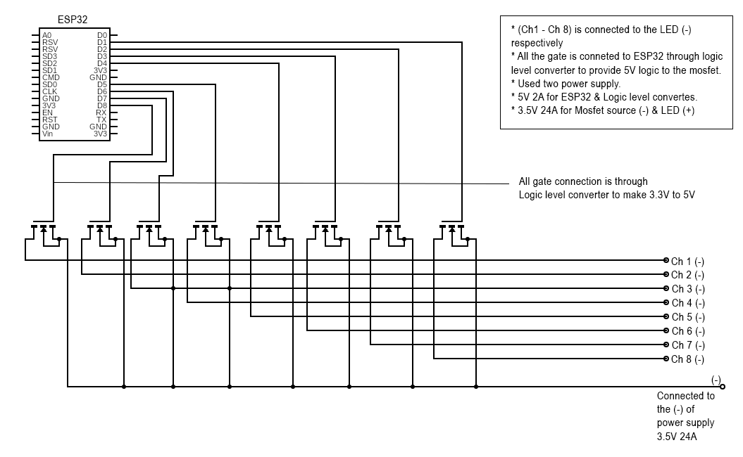
Post a full schematic if your setup.

Pete.

Use TIP31C to drive the LED. Or use IRL44N.

These can be driven directly from the GPIO. Its not recommended to do so, but i have not found any issues so far.

&

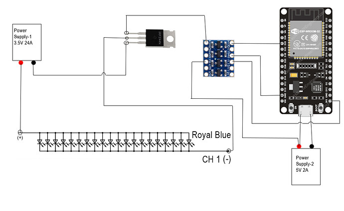
Sorry for my amateur drawing. I am not that much experienced in circuit diagram drawing. I am just doing a project for fun & most of the knowledge is from google. I couldn’t find “ESP32” diagram in the drawing tool, that’s why used “Node MCU” diagram.

I hope you will understand the diagram, as I tried to keep it as simple as possible.

But you’ve omitted quite a bit of stuff from your schematic such as how the logic level converter is wired and how you’re powering everything.
Also, the MOSFET symbols are rather weird.

If you’re wanting forum members to look at this and give some feedback then are they likely to spot any issues based on this?

Pete.

Logic level shifter is not how you drive a MOSFET gate. You should be using mosfet drivers. The frequency of pwm may be restricted by level shifter and Do not turn on the mosfet fully. This result in flickering.

EDIT: I cannot see a resistor between Gate n Source in your schematic.

1 Like

I am trying to provide the diagram of only one channel (Ch1) for reference. All the other channels are configured same way.

I didn’t use any resistors in the whole diagram.

You appear to me missing at least tow Ground connections.

It’s recommended to protect the GPIO pins on the MCU with a gate resistor to prevent over current.

As @Madhukesh has said, the logic level converter probably can’t cope with the switching frequency of the gate feed, so you should use more appropriate MOSFETs.

Pete.

1 Like

I said the same thing. You did not. And you should use one. Google “How to drive N channel MOSFET”
You will find circuits which you should be using. This problem is not related to Blynk.

Ok, I think IRLZ44N is my best bet at this moment. I ordered some on aliexpress which will take 60 days to arrive. Will test them after receiving the goods. Till then, it’s a dead end project.

Thank you Pete & Madhukesh for your kind support.

2 Likes
/*
AquArt Blynk GLOW1Tec

WRITTEN BY MARIANO PROIETTI
16 CRANE AVENUE
ISLEWORTH
MIDDLESEX, TW7 7JL
TEL. 07771 528 969
*/

//LIBRARIES//
#include <Wire.h>
#include <Adafruit_PWMServoDriver.h> 
#include <ESP8266WiFi.h>                
#include <BlynkSimpleEsp8266.h>    
//OTA//
#include <ESPAsyncTCP.h>
#include <ESPAsyncWebServer.h>
#include <AsyncElegantOTA.h>
//OTHERS//
#include <OneWire.h>
#include <DallasTemperature.h>
#include <TimeLib.h>
#include <WidgetRTC.h>
#include <EEPROM.h>
BlynkTimer timer;
WidgetRTC rtc;
AsyncWebServer serverOTA(80);

//COLOURS//
#define Purple "#a832a8"

//TIME VARIABLES
unsigned long TotalSecs;
int Hr;
int Min;
int Sec;
int DAY = 86400L;

//PWM SERVO DRIVER
Adafruit_PWMServoDriver pwm = Adafruit_PWMServoDriver();

//PIN ASSIGNMENTS//
#define HSinkFan D0      //Heat sink fan pin
#define ONE_WIRE_BUS D4  //Temp sensor pin

//WIFI Variables
int ReCnctFlag;         //Reconnection Flag

char auth[] = "0d10d17a44c94f3795fd5d7c36206bf1";
//char ssid[] = "proietti office";
char ssid[] = "AquArt";
char pass[] = "Mariano3565";

char server[] = "blynk-cloud.com";            //URL for Blynk Cloud Server
int port = 8080;

//BRIDGE WIDGET//
WidgetBridge Master_Device(V62);

//LED FADE GLOBALS & VARIABLES//
int BTNmode;
int svBTNmode;
float progress;
float Average;
float TotalAverage;
int TotalPWM;
float ChartData;
unsigned long brightness;

//CHANNEL 1//
unsigned long CH1S;
unsigned long CH1E;
unsigned long CH1Start;
unsigned long CH1End;
unsigned long FadeINmin1;
unsigned long FadeINsecs1;
unsigned long FadeOUTmin1;
unsigned long FadeOUTsecs1;
int maxPWM1;
int PWM1;
unsigned long CH1Period;
unsigned long svCH1Start;
unsigned long svCH1End;
unsigned long svFadeINsecs1;
unsigned long svFadeOUTsecs1;
int svPWM1;
float C1prog;


//CHANNEL 2//
unsigned long CH2S;
unsigned long CH2E;
unsigned long CH2Start;
unsigned long CH2End;
unsigned long FadeINmin2;
unsigned long FadeINsecs2;
unsigned long FadeOUTmin2;
unsigned long FadeOUTsecs2;
int maxPWM2;
int PWM2;
unsigned long CH2Period;
unsigned long svCH2Start;
unsigned long svCH2End;
unsigned long svFadeINsecs2;
unsigned long svFadeOUTsecs2;
int svPWM2;
float C2prog;

//CHANNEL 3//
unsigned long CH3S;
unsigned long CH3E;
unsigned long CH3Start;
unsigned long CH3End;
unsigned long FadeINmin3;
unsigned long FadeINsecs3;
unsigned long FadeOUTmin3;
unsigned long FadeOUTsecs3;
int maxPWM3;
int PWM3;
unsigned long CH3Period;
unsigned long svCH3Start;
unsigned long svCH3End;
unsigned long svFadeINsecs3;
unsigned long svFadeOUTsecs3;
int svPWM3;
float C3prog;

//CHANNEL 4//
unsigned long CH4S;
unsigned long CH4E;
unsigned long CH4Start;
unsigned long CH4End;
unsigned long FadeINmin4;
unsigned long FadeINsecs4;
unsigned long FadeOUTmin4;
unsigned long FadeOUTsecs4;
int maxPWM4;
int PWM4;
unsigned long CH4Period;
unsigned long svCH4Start;
unsigned long svCH4End;
unsigned long svFadeINsecs4;
unsigned long svFadeOUTsecs4;
int svPWM4;
float C4prog;

//CHANNEL 5//
unsigned long CH5S;
unsigned long CH5E;
unsigned long CH5Start;
unsigned long CH5End;
unsigned long FadeINmin5;
unsigned long FadeINsecs5;
unsigned long FadeOUTmin5;
unsigned long FadeOUTsecs5;
int maxPWM5;
int PWM5;
unsigned long CH5Period;
unsigned long svCH5Start;
unsigned long svCH5End;
unsigned long svFadeINsecs5;
unsigned long svFadeOUTsecs5;
int svPWM5;
float C5prog;

//CHANNEL 6//
unsigned long CH6S;
unsigned long CH6E;
unsigned long CH6Start;
unsigned long CH6End;
unsigned long FadeINmin6;
unsigned long FadeINsecs6;
unsigned long FadeOUTmin6;
unsigned long FadeOUTsecs6;
int maxPWM6;
int PWM6;
unsigned long CH6Period;
unsigned long svCH6Start;
unsigned long svCH6End;
unsigned long svFadeINsecs6;
unsigned long svFadeOUTsecs6;
int svPWM6;
float C6prog;

//TEMPERATURE ATTRIBUTES & VARIABLES//
OneWire oneWire(ONE_WIRE_BUS);
DallasTemperature sensors(&oneWire);
float tempHSink;
byte tempHSinkSetPoint = 40;
boolean TempAlarm = false;

//CONNECT TO BLYNK SERVER//
BLYNK_CONNECTED()
{
  Blynk.syncAll();
  Master_Device.setAuthToken("9b67012003144e4b874fa61a5e57e935");   //MASTER
  rtc.begin();
  Blynk.virtualWrite(V105, WiFi.localIP().toString(),"/update");
  Blynk.setProperty(V38, "color", "#a832a8");
}

void setup()
{
  Serial.begin(115200);

  WiFi.begin(ssid, pass);
  Blynk.config(auth, server, port);
  Blynk.connect();
  EEPROM.begin(160);

  //OTA////////////////////////////////////////////////////////
  serverOTA.on("/", HTTP_GET, [](AsyncWebServerRequest *request)
  {
    request->send(200, "text/plain", "AquArt DOSETec");
  });
  //Serial.println(WiFi.localIP());
  AsyncElegantOTA.begin(&serverOTA);
  serverOTA.begin();
  /////////////////////////////////////////////////////////////
  
  pwm.begin();
  pwm.setPWMFreq(100);
  Wire.setClock(400000);
  
  pinMode(ONE_WIRE_BUS, INPUT);
  pinMode(HSinkFan, OUTPUT);
  sensors.begin();
  setSyncInterval(DAY);
  Sync();
 
  timer.setInterval(2000L, HeatSink);
  timer.setInterval(450L, LEDFunction);
  timer.setInterval(500L, ClockFunction);
  timer.setInterval(700L, GraphData);
}

void loop()
{
  timer.run();
  if (Blynk.connected())
  {
    Blynk.run();
  }
  else if (ReCnctFlag == 0)
  {
    ReCnctFlag = 1;
    timer.setTimeout(5000L, []()
    {
      ReCnctFlag = 0;
      Blynk.connect();
    });
  }
}
//END//