even though it turned out to be a simple code at the end - I was thrilled that after many hours of investigation and testing I finally got my Mailbox notifier to work. It wakes from deep sleep triggered by a reed switch.
Now I hooked it to a battery (I have tried both 3xAAA and 1x18650) but now it does not wake up from deep sleep.
3x AAA will give you 4.5v and 1x18650 will give you 3.7v
You’re applying this voltage to the 5v pin, which is then being stepped down to 3.3v by the internal voltage regulator and it’s associated circuitry to power the ESP32 chip.
3.7v from the 18650 certainly isn’t enough to achieve the required voltage at the ESP32, and it seems that the 4.5v from the AAA batteries isn’t enough either.
You might get away with applying the 3.7v from the 18650 to the 3v3 pin, especially if it’s slightly undercharged, but don’t blame me if you release the magic blue smoke.
“The guy with the Swiss accent” has shared quite a few thoughts on this over the years. Here’s one example…
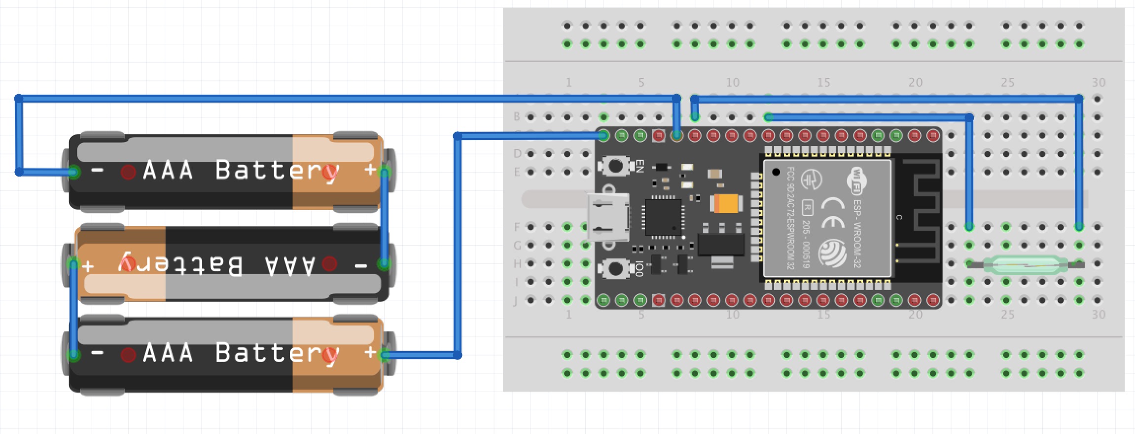
You’re connecting the battery not correctly and to the wrong pin.
The + is OK (to VIN), the - is not connected to GND, but to GPIO13 !!!.
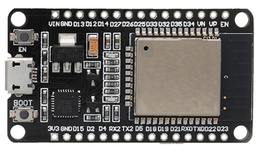
Please check the ESP32 pinout at
4xAAA connected to VIN did not help either. I could trial/error on using another GPIO for the reed…would that make sense? It is working on this GPIO when usb powered…
4xAAA connected to VIN did not help either. I could trial/error on using another GPIO for the reed…would that make sense? It is working on this GPIO when usb powered…
Could also be it is triggering, just that it does not reconnect; If I try “connect” instead, is it just replacing the “begin”?
Unfortuneately I am still struggling with this project.
3 AAA or a 18650 battery last only 24 hours (I have not trued LifePo or 3 AAA yet). During this time everything is working fine and swiftly. Blynk notifies me - after that I think the battery level is too low.
So I am thinking there might be a couple of issues - I would be happy if anyone could help me along to solve.
Here are some things on my mind:
The ESP32 draws too much current / is not properly in deep sleep mode. I have a multimeter, but where would I but the red/black wire to test?
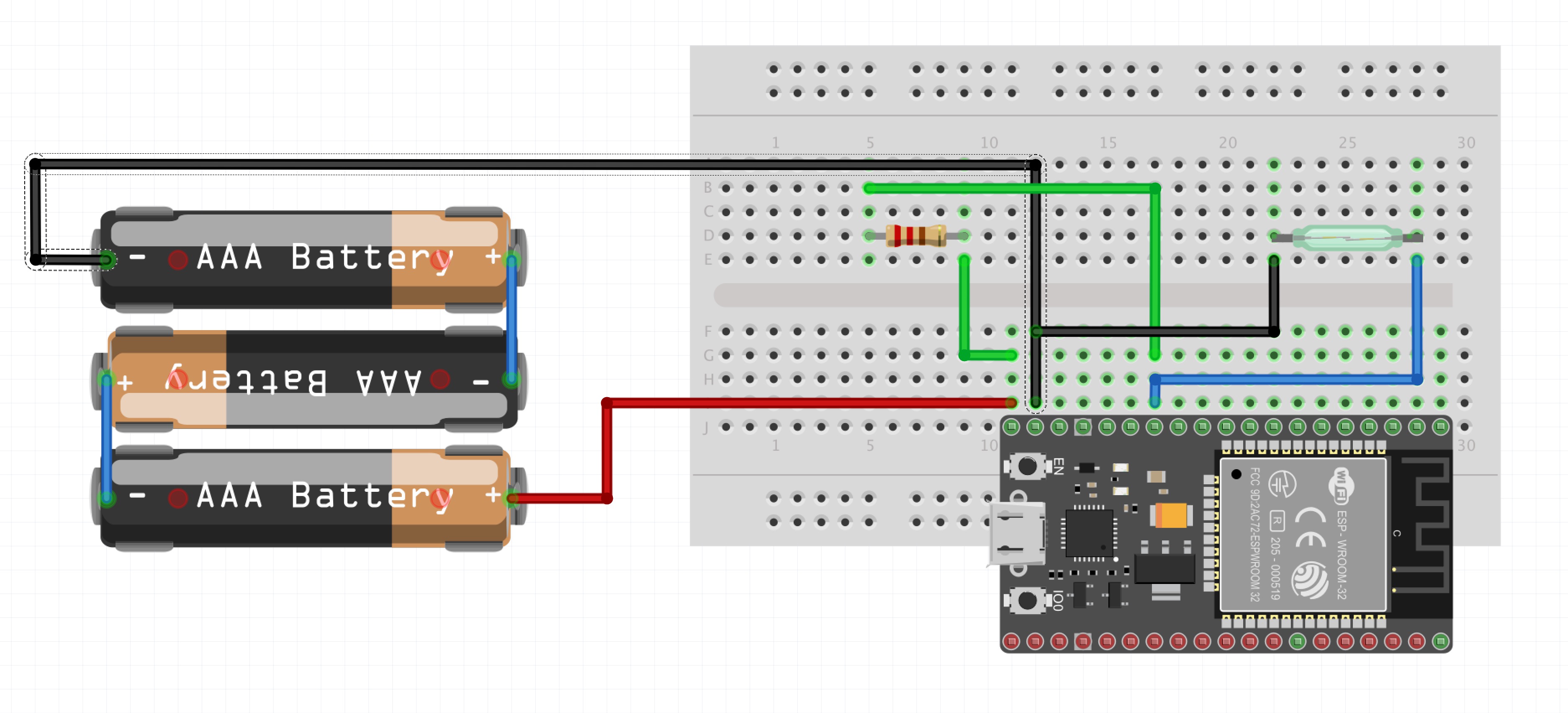
When I added the 10K resistor (which I did not use when powered via USB) I got the wake-up to work. But I am not an electric engineer and do not know much about this - so was that a bad idea? Should I use another resistor size…?
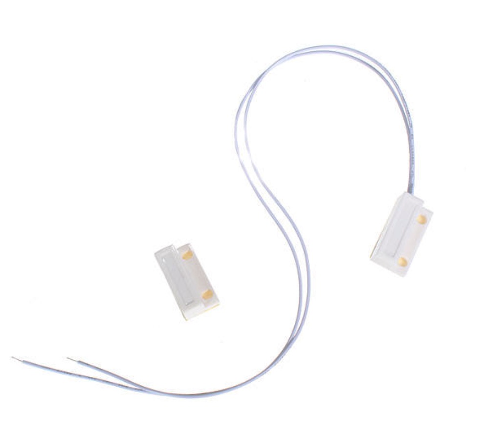
The Reed switch. I am using a Normally Closed switch - like the one in the picture. Should I try the other way around. So make the trigger be on closed - and then activate by making the Reed touch? I think this because of the drawer current…
Other good tips to try?
Thanks a lot for input!
(By the way - how do I change the tag from “Solved”?)
To test current, the multimeter needs to be on the current range *and the leads plugged into the correct sockets) and the meter needs to be inserted into the wire that has the current flowing down it. In your diagram, break the red wire and insert your multimeter in the break.
It would also be worth measuring the current flowing down the blue wire (as a separate exercise of course).
Measure both in wake and sleep mode.
The reed switch is connected between your GPIO and GND, pulling the GPIO pin LOW. Your code will trigger when the pin goes HIGH, but when you stop pulling it LOW (i.e when you open the switch) it goes to a sort of floating state that’s neither LOW or HIGH. The 10k resistor (the value is about right) connected between the pin and 3v3 will pill the GPIO pin HIGH and trigger the interrupt.
The 10k resistor, which is effectively connected between 3v3 and GND will allow 0.33ma to flow to GND, which will drain the battery at 0.33ma per hour, or less than 8ma per day, which is negligible
What I don’t know is what the effect of connecting the GPIO pin to GND, but measuring the current down the blue wire will tell you this.
I’ve never used deep sleep on the ESP32, but on the ESP8266 you need to add a small delay after the esp_deep_sleep_start(); command to allow the device to actually go to sleep, otherwise it just skips to the next line of code. Is the “This will never be printed” line appearing in your serial monitor?
using 4 AAA I now measure the consumption to about 165-170. But now the damn thing () does not go into deep sleep…it just stays on and does not notify on Blynk either.
After disconnecting the multimeter - all works again.
@CeeeWeee, you may want to read this. It has an example of code, along with a wiring diagram similar to what you are doing (although they use a push button instead of a reed switch). Check out the section: External Wake Up (ext 0).
Also, keep in mind that if you are powering through the 5V pin, you will always be powering the LDO (AM1117, on most Espressif boards). While this does have a relatively low quiescent current (5-11mA), there are some better ones on the market. Usually with battery powered devices, you want the sleep current to be in the uA.
i made some progress today - thanks to both Pete and Toro.
First I managed to measure how much the Reed draws. It measures 27 (guess that is mA).
Then I tried the 3.3 Volt - and it worked fine. Now with a single LifePo.
I can measure that it draws around 110 - so that is significantly lower than the 165.
Problem is still that when I put the multimeter in between, it will not go to sleep - and not even do the initial Blynk shout.
I will leave this for today and see if this setup (using the 3.3V) makes the battery last longer. Friday (I do not have time before) I will make a simple sketch just putting the E32 to sleep…and measure it in that state…
I am awaiting another ESP32 board - for now I am simply concluding that this board does not power down when going into Deep Sleep.
I used this very simple example - and the Reed wakes it as it should. ON PC USB POWER - and there I cannot really measure the consumption right?
When putting the exact same setup on 4 x AAA via the 3.3 V the consumption is ~150…
It is absolutely possible that I am doing something wrong - but the next test will be on a new ESP32 board …
Deep Sleep with External Wake Up
=====================================
This code displays how to use deep sleep with
an external trigger as a wake up source and how
to store data in RTC memory to use it over reboots

This code is under Public Domain License.

Hardware Connections
======================
Push Button to GPIO 33 pulled down with a 10K Ohm
resistor

NOTE:
======
Only RTC IO can be used as a source for external wake
source. They are pins: 0,2,4,12-15,25-27,32-39.

Author:
Pranav Cherukupalli <cherukupallip@gmail.com>
*/

#define BUTTON_PIN_BITMASK 0x200000000 // 2^33 in hex

RTC_DATA_ATTR int bootCount = 0;

/*
Method to print the reason by which ESP32
has been awaken from sleep
*/
void print_wakeup_reason(){
  esp_sleep_wakeup_cause_t wakeup_reason;

  wakeup_reason = esp_sleep_get_wakeup_cause();

  switch(wakeup_reason)
  {
    case ESP_SLEEP_WAKEUP_EXT0 : Serial.println("Wakeup caused by external signal using RTC_IO"); break;
    case ESP_SLEEP_WAKEUP_EXT1 : Serial.println("Wakeup caused by external signal using RTC_CNTL"); break;
    case ESP_SLEEP_WAKEUP_TIMER : Serial.println("Wakeup caused by timer"); break;
    case ESP_SLEEP_WAKEUP_TOUCHPAD : Serial.println("Wakeup caused by touchpad"); break;
    case ESP_SLEEP_WAKEUP_ULP : Serial.println("Wakeup caused by ULP program"); break;
    default : Serial.printf("Wakeup was not caused by deep sleep: %d\n",wakeup_reason); break;
  }
}

void setup(){
  Serial.begin(115200);
  delay(1000); //Take some time to open up the Serial Monitor

  //Increment boot number and print it every reboot
  ++bootCount;
  Serial.println("Boot number: " + String(bootCount));

  //Print the wakeup reason for ESP32
  print_wakeup_reason();

  /*
  First we configure the wake up source
  We set our ESP32 to wake up for an external trigger.
  There are two types for ESP32, ext0 and ext1 .
  ext0 uses RTC_IO to wakeup thus requires RTC peripherals
  to be on while ext1 uses RTC Controller so doesnt need
  peripherals to be powered on.
  Note that using internal pullups/pulldowns also requires
  RTC peripherals to be turned on.
  */
  esp_sleep_enable_ext0_wakeup(GPIO_NUM_33,1); //1 = High, 0 = Low

  //If you were to use ext1, you would use it like
  //esp_sleep_enable_ext1_wakeup(BUTTON_PIN_BITMASK,ESP_EXT1_WAKEUP_ANY_HIGH);

  //Go to sleep now
  Serial.println("Going to sleep now");
  esp_deep_sleep_start();
  Serial.println("This will never be printed");
}

void loop(){
  //This is not going to be called
}


 ) does not go into deep sleep…it just stays on and does not notify on Blynk either.
 …
…