You can measure power consumption when powered by the PC in one of two ways…
Hack a USB cable by stripping off the outer layer and locate the positive wire (usually red) or negative wire (usually black) and cut that cable and intern your multimeter in line with the wire.
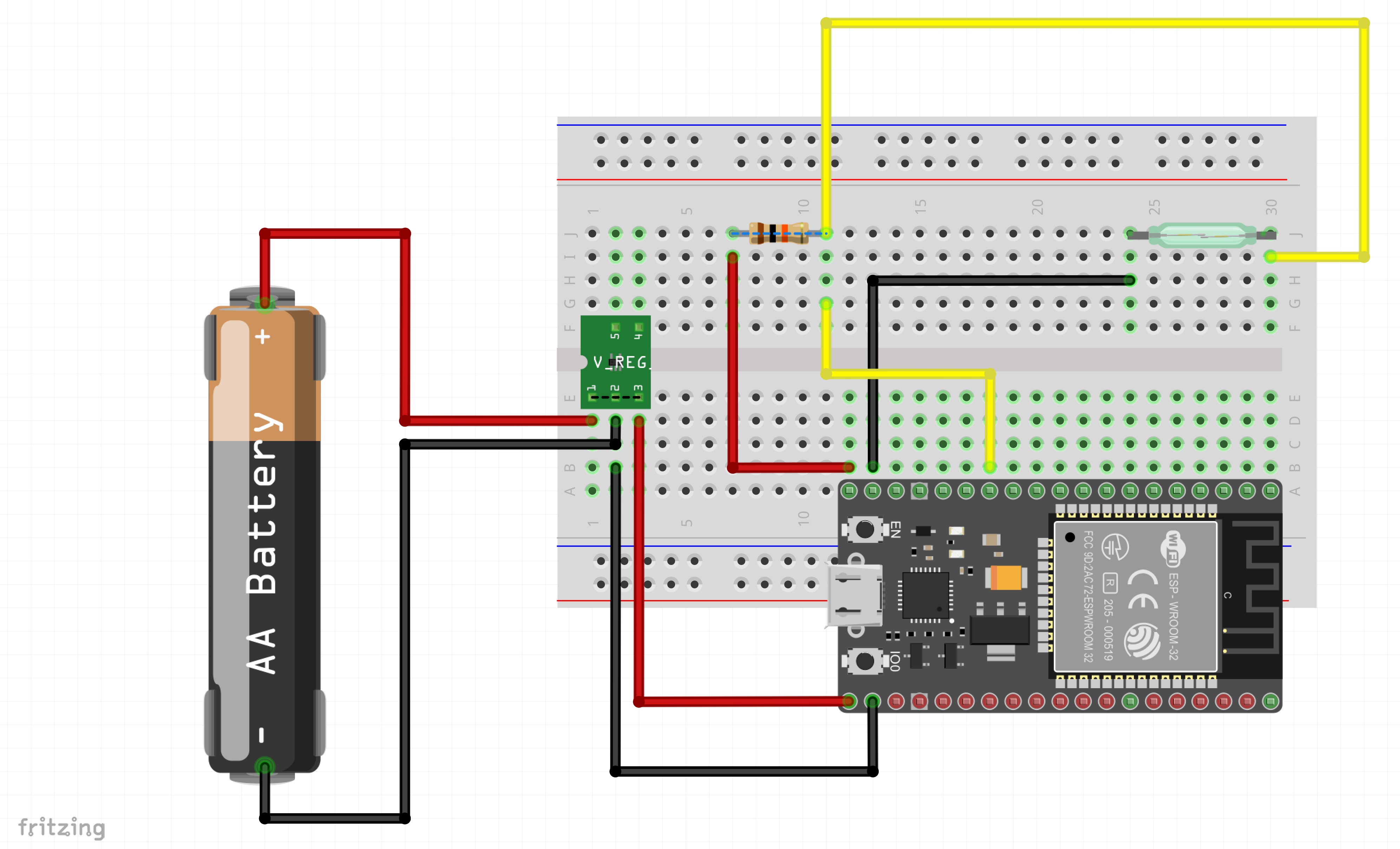
Assuming these are hooked up in series, 4*1.5V = 6V, way too much to apply to the 3.3V pin. It may be possible you fried something, and if you haven’t you might if you keep it up. The 3.3V needs exactly that, 3.3V. Which is why the Dev boards use a LDO to regulate the incoming voltage to 3.3V. If you want to power it through the 3.3V pin, you need to have a stable 3.3V source.
I suggest powering it through the 5V pin, and testing it that way. If battery life is not what you are expecting look into a voltage regulator that consumes less current when no power is being drawn (i.e. when board is asleep). Maybe something like THIS. This would be a good one if using a LIPO type battery, ( or 3 x AAA) as it will reduce the voltage when the battery is fully charged (4.2V LIPO, 4.5V 3 x AAA), and increase in as the battery as it nears being drained (2.8V-3.0V). Just make sure if you are using a LIPO battery that it has the required protection circuits for preventing over-discharge.
Thanks again guys - I have ordered some of these Pololu’s and a USB Power meter…
When the new board arrives it will only be powered by USB, via the Pololu or via this one set to 3.3V.
I never paid much attention to 3.3V - 5V - or what the components need. Explains why some other projects seem to be off…like humidity and temperature sensors …Of course stupid now looking back…one has to learn.
In stock I also have tried a 3.2V AA 14500 LiFePO4…but that might have been slightly on the low side then. (and I might have ruined the board before that).
I found and old post I have read ages ago…now this seems to put new light on my problem - and gives me some new ideas. Even though it is based on ESP8266 it certainly should inspire.
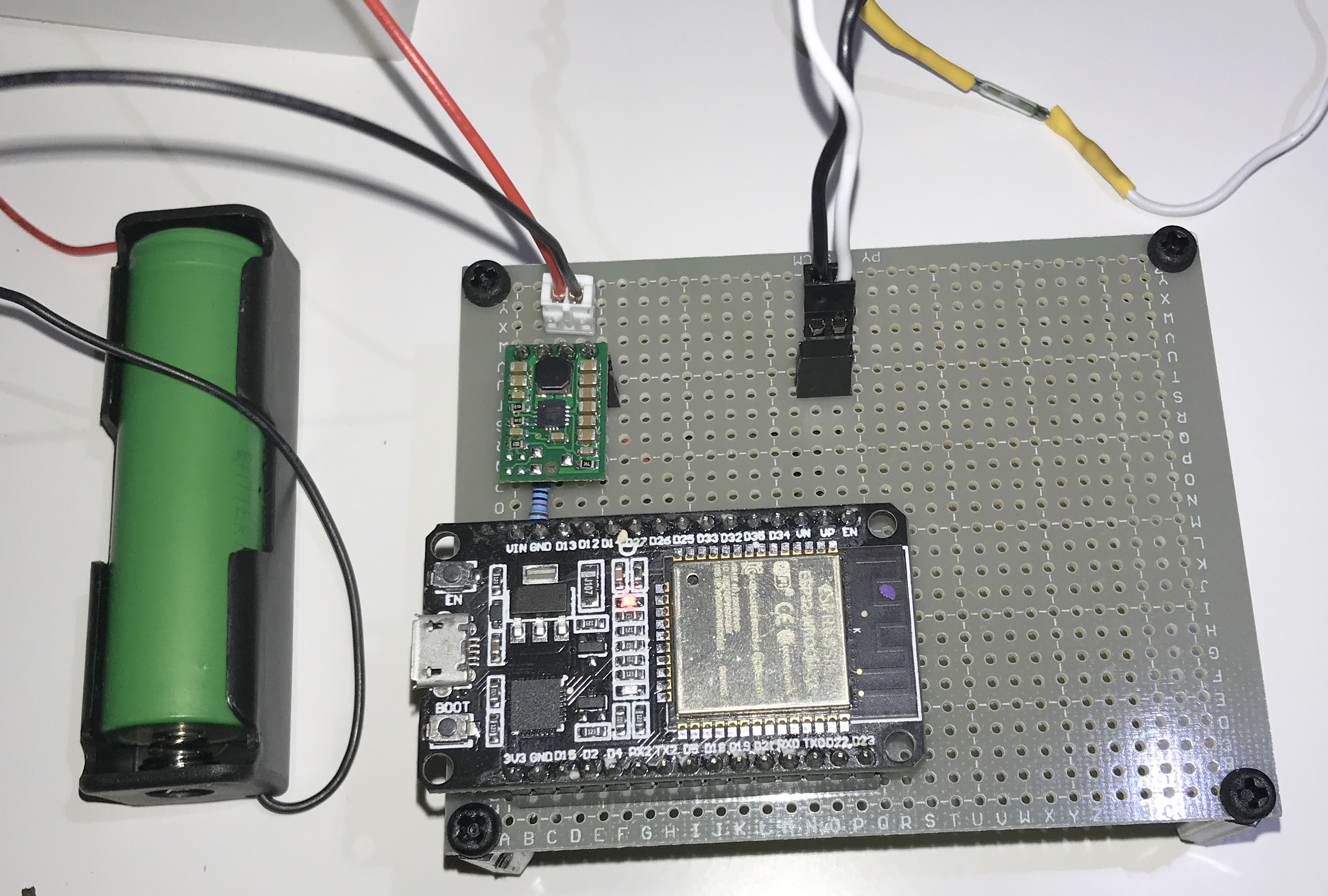
Now with Pololu 3.3V and a new Reed switch (now with Normally Open). I prepared my PCB to be able with a battery connector to easy be able to try out both a AA LifePo 3.2 and an 18650 3.7…
Right now the 18650 is connected - it is working. But I wonder for how many hours. Power Consumption seems to be around 20mA even in Deep Sleep still
#define BLYNK_PRINT Serial

#include <WiFi.h>
#include <WiFiClient.h>
#include <BlynkSimpleEsp32.h>

char auth[] = "d06d22527eb04ee285667929a4be04f3";
char ssid[] = "mine";
char pass[] = "mine";

void setup()
{
  // Debug console
  Serial.begin(115200);
  WiFi.disconnect();
  delay(10000);
  //WiFi.begin("mine","mine");
  Blynk.begin(auth, ssid, pass);
  Blynk.notify("Der er post i postkassen");
  Blynk.run();
  //Blynk.disconnect();
  WiFi.disconnect();
  esp_sleep_enable_ext0_wakeup(GPIO_NUM_26,0); //1 = High, 0 = Low
  Serial.println("Going to sleep now");
  esp_deep_sleep_start();

  Serial.println("This will never be printed");
}

void loop()
{

}
´´´

I did receive a new ESP32 Board - the ESP32-CAM. I could not find my USB-converter but found to upload code via the Arduino Nano...anyway, did not try that board with this setup yet.
I have seen this and I guess you especially mean the mention of the Firebeetle. I ordered a Firebeetle 2 days ago (and a SparkFun Esp32 Thing). I am also looking into using different types of LDO’s. Will keep you postes on that.
But for sure I have high hopes for the Firebeetle.
The article said that they were getting 19ma in sleep mode with the board they were using and this is very similar to your results.
Removing the LED from your board might save 1-2ma, but I think the main loss is in the voltage regulator circuit.
Our friend with the Swiss accent has a few videos on the deep sleep suitability of a variety of boards.
Hi there, I’ve done a similar mail box project but used a small 5v solar panel, 18650 battery, PIR, ultrasonic sensor and of course the old faithful ESP8266 chip. The good thing about the PIR is that the esp draws no current until the mail enters the mailbox triggering it and booting the system up. The ultrasonic is used to measure distance so if the measurement is say less than 10cm I get notified that I have mail. It’s been running for close to two years now without issues.
I think you are both right. My not so precise measurements via USB said 0.02A - which is 20mA. Upon connection to Wifi and Blink it reads 140mA…then down to 20mA again. I will try to see the reading after I take off the LED. But have not much time the next days (work takes a lot of my free time ). I also have another Voltage Regulator coming up like this. And of course still have the Firebeetle coming soon. Lots of interesting options. Now I am getting stubborn and want this thing to work
This is very interesting. Do you have more information on your setup? Board, components etc.? Maybe a description somewhere?
It is about time I post an update to this post…how did it work out for me?
I quit - I failed…I was utterly defeated in trying to make my Mailbox Notifier work using batteries.
I never got it to work properly - and I bought many different boards, polulus etc. It was all good fun…but it would always draw too much power to work for a couple of months. This is purely because of my own abilities…I am sure someone would get it to work…
During December I started to dive into Home Assistant - initially for other reasons than my mailbox, as you will know Home Assistant can support lots of different tasks. I use it for Phillips Hue, Sonoff and ESP8266 with temperature probes. Now, I stumbled upon Sonoff’s Bridge…and…yes…there was the answer to my mailbox problem.
 …Of course stupid now looking back…one has to learn.