I am a complete noob in terms of coding. So, i am sorry if my question is inappropriate.
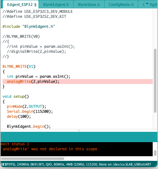
I have been trying to make a wifi led controller using Espressif ESP32 WROOM board. Initially i started with a simple switch for the GPIO 2 (Blue led on board) with blynk.edgent example for esp32 (Code image attached). It worked like a charm.
Then i wanted to control the led brightness using slider widget. I made a new datastream on V1 (Data type: Integer, Min:0, Max: 255).
Then tried to analogWrite the pin inside the code (as attached but failed to compile)
It would be much appreciated if anyone could help me out.
Sorry (as a new user, i can only upload 1 image in my post, I uploaded the error one, the working code is greyed out in the same screenshot (V0))
Complete Goal (Optional Help):
I want to make an LED Light, where i will be able to control 8 Channel of led using 8 different slider. & 1 master slider to control all the channel brightness. 1 master switch to turn off/on all the channels all-together.
Lastly, i need timer option, where i can set time to turn off/on to all the led’s with their last slider values/ settings.
If someone wants to assist me to complete my project, it will be really helpful to me.
Thanks for the feed back. I already tried those methods for offline websocket pwm control. But I can’t figure out how to implement them inside the blynk code.
I successfully managed to add 8 sliders and assigned them to separate pins. Thanks to both of you for guiding me (@John93 & @PeteKnight ).
For others if it helps, I am uploading the code I used.
// Fill-in information from your Blynk Template here
#define BLYNK_TEMPLATE_ID "TMPLVGYI9Pqm"
#define BLYNK_DEVICE_NAME "DIY G5 Blue T"

#define BLYNK_FIRMWARE_VERSION        "0.1.0"

#define BLYNK_PRINT Serial
//#define BLYNK_DEBUG

#define APP_DEBUG

// Uncomment your board, or configure a custom board in Settings.h
//#define USE_WROVER_BOARD
//#define USE_TTGO_T7
//#define USE_ESP32C3_DEV_MODULE
//#define USE_ESP32S2_DEV_KIT

#include "BlynkEdgent.h"

int ledPin1 = 2;  //33
int ledPin2 = 12;
int ledPin3 = 13;
int ledPin4 = 14;
int ledPin5 = 25;
int ledPin6 = 26;
int ledPin7 = 27;
int ledPin8 = 32;
int ledPin9 = 33;

const int chn1 = 0;
const int chn2 = 1;
const int chn3 = 2;
const int chn4 = 3;
const int chn5 = 4;
const int chn6 = 5;
const int chn7 = 6;
const int chn8 = 7;
const int chn9 = 8;

const int frq = 3000;
const int res = 8;

BLYNK_WRITE(V0)
{
  int pinValue = param.asInt(); // assigning incoming value from pin V1 to a variable
  // You can also use:
  // String i = param.asStr();
  // double d = param.asDouble();
  ledcWrite(chn1, pinValue);
  Serial.print("V0 Slider value is: ");
  Serial.println(pinValue);
  delay(30);
}

BLYNK_WRITE(V1)
{
  int pinValue = param.asInt(); // assigning incoming value from pin V1 to a variable
  // You can also use:
  // String i = param.asStr();
  // double d = param.asDouble();
  ledcWrite(chn2, pinValue);
  Serial.print("V1 Slider value is: ");
  Serial.println(pinValue);
  delay(30);
}

BLYNK_WRITE(V2)
{
  int pinValue = param.asInt(); // assigning incoming value from pin V1 to a variable
  // You can also use:
  // String i = param.asStr();
  // double d = param.asDouble();
  ledcWrite(chn3, pinValue);
  Serial.print("V2 Slider value is: ");
  Serial.println(pinValue);
  delay(30);
}

BLYNK_WRITE(V3)
{
  int pinValue = param.asInt(); // assigning incoming value from pin V1 to a variable
  // You can also use:
  // String i = param.asStr();
  // double d = param.asDouble();
  ledcWrite(chn4, pinValue);
  Serial.print("V3 Slider value is: ");
  Serial.println(pinValue);
  delay(30);
}

BLYNK_WRITE(V4)
{
  int pinValue = param.asInt(); // assigning incoming value from pin V1 to a variable
  // You can also use:
  // String i = param.asStr();
  // double d = param.asDouble();
  ledcWrite(chn5, pinValue);
  Serial.print("V4 Slider value is: ");
  Serial.println(pinValue);
  delay(30);
}

BLYNK_WRITE(V5)
{
  int pinValue = param.asInt(); // assigning incoming value from pin V1 to a variable
  // You can also use:
  // String i = param.asStr();
  // double d = param.asDouble();
  ledcWrite(chn6, pinValue);
  Serial.print("V5 Slider value is: ");
  Serial.println(pinValue);
  delay(30);
}

BLYNK_WRITE(V6)
{
  int pinValue = param.asInt(); // assigning incoming value from pin V1 to a variable
  // You can also use:
  // String i = param.asStr();
  // double d = param.asDouble();
  ledcWrite(chn7, pinValue);
  Serial.print("V6 Slider value is: ");
  Serial.println(pinValue);
  delay(30);
}

BLYNK_WRITE(V7)
{
  int pinValue = param.asInt(); // assigning incoming value from pin V1 to a variable
  // You can also use:
  // String i = param.asStr();
  // double d = param.asDouble();
  ledcWrite(chn8, pinValue);
  Serial.print("V7 Slider value is: ");
  Serial.println(pinValue);
  delay(30);
}

BLYNK_WRITE(V8)
{
  int pinValue = param.asInt(); // assigning incoming value from pin V1 to a variable
  // You can also use:
  // String i = param.asStr();
  // double d = param.asDouble();
  ledcWrite(chn8, pinValue);
  Serial.print("V8 Slider value is: ");
  Serial.println(pinValue);
  delay(30);
}

void setup()
{
  ledcSetup(chn1,frq,res);
  ledcSetup(chn2,frq,res);
  ledcSetup(chn3,frq,res);
  ledcSetup(chn4,frq,res);
  ledcSetup(chn5,frq,res);
  ledcSetup(chn6,frq,res);
  ledcSetup(chn7,frq,res);
  ledcSetup(chn8,frq,res);
  ledcSetup(chn9,frq,res);

  ledcAttachPin(ledPin1,chn1);
  ledcAttachPin(ledPin2,chn2);
  ledcAttachPin(ledPin3,chn3);
  ledcAttachPin(ledPin4,chn4);
  ledcAttachPin(ledPin5,chn5);
  ledcAttachPin(ledPin6,chn6);
  ledcAttachPin(ledPin7,chn7);
  ledcAttachPin(ledPin8,chn8);
  ledcAttachPin(ledPin9,chn9);

  Serial.begin(115200);
  delay(100);

  BlynkEdgent.begin();
}

void loop() {
  BlynkEdgent.run();
}
I also attached a main power switch to turn all the channels off/on using below code, which doesn’t seem to be working.
Now, There are few things i want to add 1 by 1 if you guys can help me.
Very important: Whenever the electric power is disconnected & then re-connected I want the device to automatically get back to the last value they had before shutting down.
Want the V9 switch to turn off all the slider virtual pins & when turned on, i want all the sliders to get back to their last value. (the value they individually carried before turning off)
Declare your pinValue as a global variable (you will need a unique name for each, i.e. pinValue1, pinValue2, etc.). Add a check (if statement) in your BLYNK_WRITE function to see if the Master Switch is on or off. Modify your BLYNK_WRITE(V9) so that when it turns on it writes the pin to the pinValue for each pin.
For Example:
int button_v9_value;
int pinValue1;
int pinValue2;

BLYNK_WRITE(V1)
{
 pinValue1 = param.asInt(); // assigning incoming value from pin V1 to a variable
  // You can also use:
  // String i = param.asStr();
  // double d = param.asDouble();
if (button_v9_value == 0)
{
  ledcWrite(chn1, pinValue1);
  Serial.print("V1 Slider value is: ");
  Serial.println(pinValue1);
  delay(30);
}
}

BLYNK_WRITE(V9)
    {
   button_v9_value = param.asInt(); //assuming 1 is sent when pressed, and pressed equals all off
  if(button_v9_value == 1)  //turn all off
    {
      ledcWrite(chn1, 0);
      ledcWrite(chn2, 0);
      //add all 8, etc.

    }
  else //turn all on to slider value
    {
      ledcWrite(chn1, pinValue1);
      ledcWrite(chn2, pinValue2);
      //add all 8, etc.

    }
}
Thank You @John93
I understood the way of making it possible. But came across a silly problem.
I am using Edgent_esp32 example for the project. inside all the tabs I couldn’t find the “BLYNK_CONNECTED()” line to put “Blynk.syncAll()” inside.
I know it’s a silly favour to ask, but can you tell me where i can find this line in the Edgent example?
It worked exactly as I wanted. With this solution, initially, all my requirements have been full filled. If needed, This case can be marked as solved.
Additional Requirements:
If asking another question in the same thread is prohibited then please let me know, I will open a new thread, or else please help to solve the llast question.
I want to add a timer option, where i can manually input on/ off time for the V9 switch. How can i do that? with which widget? Code example?
Thank you for all the help from the community.
For others, I am uploading the full sketch code if they need it for any reason.
// Fill-in information from your Blynk Template here
#define BLYNK_TEMPLATE_ID "Template ID"
#define BLYNK_DEVICE_NAME "Device Name"
#define BLYNK_FIRMWARE_VERSION "0.1.0"
#define BLYNK_PRINT Serial
//#define BLYNK_DEBUG
#define APP_DEBUG
// Uncomment your board, or configure a custom board in Settings.h
//#define USE_WROVER_BOARD
//#define USE_TTGO_T7
//#define USE_ESP32C3_DEV_MODULE
//#define USE_ESP32S2_DEV_KIT
#include "BlynkEdgent.h"
int ledPin1 = 2; //33
int ledPin2 = 12;
int ledPin3 = 13;
int ledPin4 = 14;
int ledPin5 = 25;
int ledPin6 = 26;
int ledPin7 = 27;
int ledPin8 = 32;
int ledPin9 = 33;
int button_v9_value;
int pinValue1;
int pinValue2;
int pinValue3;
int pinValue4;
int pinValue5;
int pinValue6;
int pinValue7;
int pinValue8;
int pinValue9;
const int chn1 = 0;
const int chn2 = 1;
const int chn3 = 2;
const int chn4 = 3;
const int chn5 = 4;
const int chn6 = 5;
const int chn7 = 6;
const int chn8 = 7;
const int chn9 = 8;
const int frq = 3000;
const int res = 8;
BLYNK_CONNECTED()
{
  Blynk.syncAll();
}
BLYNK_WRITE(V0)
{
pinValue1 = param.asInt(); // assigning incoming value from pin V1 to a variable
if (button_v9_value == 1)
{
ledcWrite(chn1, pinValue1);
Serial.print("V0 Slider value is: ");
Serial.println(pinValue1);
delay(30);
}
}
BLYNK_WRITE(V1)
{
pinValue2 = param.asInt(); // assigning incoming value from pin V1 to a variable
if (button_v9_value == 1)
{
ledcWrite(chn2, pinValue2);
Serial.print("V1 Slider value is: ");
Serial.println(pinValue2);
delay(30);
}
}
BLYNK_WRITE(V2)
{
pinValue3 = param.asInt(); // assigning incoming value from pin V1 to a variable
if (button_v9_value == 1)
{
ledcWrite(chn3, pinValue3);
Serial.print("V2 Slider value is: ");
Serial.println(pinValue3);
delay(30);
}
}
BLYNK_WRITE(V3)
{
pinValue4 = param.asInt(); // assigning incoming value from pin V1 to a variable
if (button_v9_value == 1)
{
ledcWrite(chn4, pinValue4);
Serial.print("V3 Slider value is: ");
Serial.println(pinValue4);
delay(30);
}
}
BLYNK_WRITE(V4)
{
pinValue5 = param.asInt(); // assigning incoming value from pin V1 to a variable
if (button_v9_value == 1)
{
ledcWrite(chn5, pinValue5);
Serial.print("V4 Slider value is: ");
Serial.println(pinValue5);
delay(30);
}
}
BLYNK_WRITE(V5)
{
pinValue6 = param.asInt(); // assigning incoming value from pin V1 to a variable
if (button_v9_value == 1)
{
ledcWrite(chn6, pinValue6);
Serial.print("V5 Slider value is: ");
Serial.println(pinValue6);
delay(30);
}
}
BLYNK_WRITE(V6)
{
pinValue7 = param.asInt(); // assigning incoming value from pin V1 to a variable
if (button_v9_value == 1)
{
ledcWrite(chn7, pinValue7);
Serial.print("V6 Slider value is: ");
Serial.println(pinValue7);
delay(30);
}
}
BLYNK_WRITE(V7)
{
pinValue8 = param.asInt(); // assigning incoming value from pin V1 to a variable
if (button_v9_value == 1)
{
ledcWrite(chn8, pinValue8);
Serial.print("V7 Slider value is: ");
Serial.println(pinValue8);
delay(30);
}
}
BLYNK_WRITE(V8)
{
pinValue9 = param.asInt(); // assigning incoming value from pin V1 to a variable
if (button_v9_value == 1)
{
ledcWrite(chn9, pinValue9);
Serial.print("V8 Slider value is: ");
Serial.println(pinValue9);
delay(30);
}
}
BLYNK_WRITE(V9)
// This function is triggered when the widget attached to V9 changes in the app
{
button_v9_value = param.asInt(); // get the value of the button widget and store
if(button_v9_value == 0)
{
ledcWrite(chn1,0);
ledcWrite(chn2,0);
ledcWrite(chn3,0);
ledcWrite(chn4,0);
ledcWrite(chn5,0);
ledcWrite(chn6,0);
ledcWrite(chn7,0);
ledcWrite(chn8,0);
ledcWrite(chn9,0);
}
else
{
ledcWrite(chn1, pinValue1);
ledcWrite(chn2, pinValue2);
ledcWrite(chn3, pinValue3);
ledcWrite(chn4, pinValue4);
ledcWrite(chn5, pinValue5);
ledcWrite(chn6, pinValue6);
ledcWrite(chn7, pinValue7);
ledcWrite(chn8, pinValue8);
ledcWrite(chn9, pinValue9);
}
}
void setup()
{
ledcSetup(chn1,frq,res);
ledcSetup(chn2,frq,res);
ledcSetup(chn3,frq,res);
ledcSetup(chn4,frq,res);
ledcSetup(chn5,frq,res);
ledcSetup(chn6,frq,res);
ledcSetup(chn7,frq,res);
ledcSetup(chn8,frq,res);
ledcSetup(chn9,frq,res);
ledcAttachPin(ledPin1,chn1);
ledcAttachPin(ledPin2,chn2);
ledcAttachPin(ledPin3,chn3);
ledcAttachPin(ledPin4,chn4);
ledcAttachPin(ledPin5,chn5);
ledcAttachPin(ledPin6,chn6);
ledcAttachPin(ledPin7,chn7);
ledcAttachPin(ledPin8,chn8);
ledcAttachPin(ledPin9,chn9);
Serial.begin(115200);
delay(100);
BlynkEdgent.begin();
}
void loop() {
BlynkEdgent.run();
}
For Schedule On/Off time, I added the “Timer Input” Widget and created a datastream same as a switch on V10. But when I add the widget, can’t select that datastream. It’s saying “No supported data stream”
I’d suggest that you search the forum for recent examples of how to use the Time Input widget, and how to obtain the current time from the Blynk server using Blynk IoT,
Don’t confuse yourself by looking at examples for the Timer widget, as this is no longer supported.