Hi Blynkers,
I wanted to share a small set-up using a simple RGB led with the ESP32 (Lolin32) doing PWM. This is not a “project” by itself but I guess, it could be useful to other Blynkers cause at the moment, the analogWrite() function is not implemented. It should be useful for DC motors, Robots…
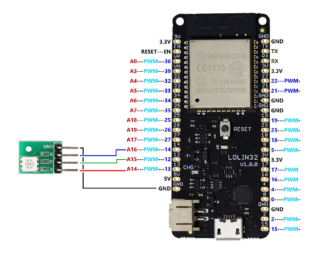
The set-up couldn’t be more simple:
The code (Remember I’m a Local Server guy, change it accordingly…):
#define BLYNK_PRINT Serial


#include <WiFi.h>
#include <WiFiClient.h>
#include <BlynkSimpleEsp32.h>
BlynkTimer timer;

//********************* SECTION FOR YOU TO COMPLETE WITH YOUR DETAILS *************
// Get Auth Token in the Blynk App.

char auth[] = "xxxxxxxx"; // Token
char cloudserver[16] = "blynk-cloud.com";
char localserver[16] = "xxx.xxx.xxx.xxx";          // Enter your IP details for the local server
char ssid[] = "xxxxxxxxxx";                   // Your WiFi credentials.
char pass[] = "xxxxxxxxxxxx";                     // Set password to "" for open networks.
//*********************************************************************************


//********************* CLOCK DETAILS *********************************************
#include <WidgetRTC.h>//Blynk
WidgetRTC rtc;
//*********************************************************************************

//********************* LED DETAILS *********************************************
uint8_t led1 = 12;
uint8_t led2 = 13;
uint8_t led3 = 14;
int PWM_LED1;
int PWM_LED2;
int PWM_LED3;
//*********************************************************************************


bool isFirstConnect = true;

BLYNK_CONNECTED() {
if (isFirstConnect) {
Blynk.syncAll();
Blynk.notify("ESP32 Starting!!");
isFirstConnect = false;
}
}


void setup()
{

ledcAttachPin(led1, 1); // assign RGB led pins to channels
ledcAttachPin(led2, 2); // assign RGB led pins to channels
ledcAttachPin(led3, 3); // assign RGB led pins to channels
  // Initialize channels
  // channels 0-15, resolution 1-16 bits, freq limits depend on resolution
  // ledcSetup(uint8_t channel, uint32_t freq, uint8_t resolution_bits);
ledcSetup(1, 12000, 12); // 12 kHz PWM, 12-bit resolution
ledcSetup(2, 12000, 12); // 12 kHz PWM, 12-bit resolution
ledcSetup(3, 12000, 12); // 12 kHz PWM, 12-bit resolution

  // Debug console
  Serial.begin(115200);
  Serial.println("\n Starting");
  //Blynk.begin(auth, ssid, pass);              // normal Blynk Cloud server connection
 // Blynk.config(auth, cloudserver);            // for Blynk's cloud server if WiFi already connected
  Blynk.begin(auth, ssid, pass, localserver);   // for a local server requiring WiFi connection
  int mytimeout = millis() / 1000;
  while (Blynk.connect() == false) {        // wait here until connected to the server
    if((millis() / 1000) > mytimeout + 8){      // try to connect to the server for less than 9 seconds
      break;                                    // continue with the sketch regardless of connection to the server
    }
  }
  rtc.begin(); //RTC clock begin
  timer.setInterval(15000, reconnectBlynk); // check every 15 seconds if we are connected to the server
  timer.setInterval(5000L, clockvalue);  // check value for time
  timer.setInterval(5000L, sendWifi);    // Wi-Fi singal

}

void reconnectBlynk() // reconnect to server if disconnected, timer checks every 15 seconds
{
  if (!Blynk.connected()) {
    if(Blynk.connect()) {
      BLYNK_LOG("Reconnected");
    } else {
      BLYNK_LOG("Not reconnected");
    }
  }
}


void sendWifi() {

 int wifisignal = map(WiFi.RSSI(), -105, -40, 0, 100);
  Blynk.virtualWrite(V10, wifisignal);

}


void clockvalue() // Digital clock display of the time
{
 int gmthour = hour();
  if (gmthour == 24){
     gmthour = 0;
  }
  String displayhour =   String(gmthour, DEC);
  int hourdigits = displayhour.length();
  if(hourdigits == 1){
    displayhour = "0" + displayhour;
  }
  String displayminute = String(minute(), DEC);
  int minutedigits = displayminute.length();
  if(minutedigits == 1){
    displayminute = "0" + displayminute;
  }

  String displaycurrenttime = displayhour + ":" + displayminute;
  Blynk.virtualWrite(V11, displaycurrenttime);
}

BLYNK_WRITE(V0) //slider in Virtual Pin 0 (0...4095)
{
 PWM_LED1 = param.asInt();
 ledcWrite(1, PWM_LED1); // write red component to channel 1, etc. 0-4095
 float voltage1 = map(PWM_LED1, 0, 4095, 0, 330);
 Blynk.virtualWrite(V3, voltage1/100);
}

BLYNK_WRITE(V1) //slider in Virtual Pin 1 (0...4095)
{
 PWM_LED2 = param.asInt();
 ledcWrite(2, PWM_LED2); // write red component to channel 1, etc. 0-4095
 float voltage2 = map(PWM_LED2, 0, 4095, 0, 330);
 Blynk.virtualWrite(V4, voltage2/100);
}

BLYNK_WRITE(V2) //slider in Virtual Pin 2 (0...4095)
{
 PWM_LED3 = param.asInt();
 ledcWrite(3, PWM_LED3); // write red component to channel 1, etc. 0-4095
 float voltage3 = map(PWM_LED3, 0, 4095, 0, 330);
 Blynk.virtualWrite(V5, voltage3/100);
}

void loop()
{
if (Blynk.connected()) {   // to ensure that Blynk.run() function is only called if we are still connected to the server
    Blynk.run();
}
timer.run();
}
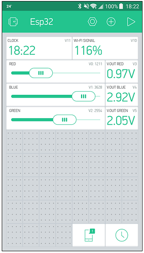
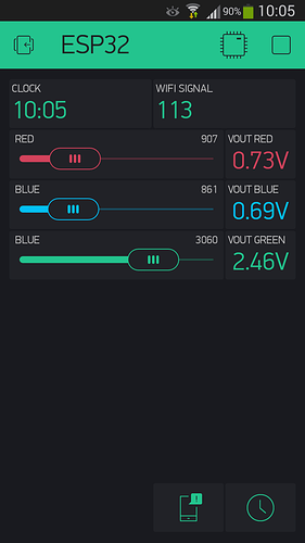
The dashboard:
(I’m sorry but at the moment there’s no way to Clone the Project properly)
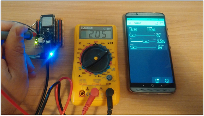
Other picture showing the result of the tester VS the V.out calculated in the code (2.05V vs 2.09V, quite good!)
The video:
I hope you like it!!
