I just got OTA working with my 1M version of ESP-01. My ESP is currently connected to an adapter I purchased for bidirectional logic level conversion of RX and TX as well as voltage regulation from 5v to 3.3v. Now that I have RX and TX freed up with OTA, I’m wondering if it’s possible to use the RX or TX line as a 5v digital input/output line on the high voltage side of my ESP-01 adapter. And what arduino code would be necessary to achieve this. I’m trying to use one of these lines as the data signal for addressable led strip.
Yes, it’s possible, if question is if you can use RX and TX as regular GPIO ports. TX is on GPIO1, RX on GPIO3. But I’m afraid I didn’t understand your question well. What do you mean by ‘high voltage side of your ESP01’?
Useful info on additional pins for the very restrictive ESP-01 https://www.forward.com.au/pfod/ESP8266/GPIOpins/ESP8266_01_pin_magic.html
By high voltage side I mean I want the output to be 5v not 3.3v. So I would want to make use of the logic level conversion that’s already happening on the RX and TX lines as part of my ESP-01 adapter.
So for gpio1 or gpio3, would I just use pinMode(1, output) or pinMode(3,output) in arduino? And make sure there aren’t any Serial.begin or Serial.println() commands.
Ok, so if you are planning to use TX and RX to contol relays, it’s ok and you don’t need 5V GPIO output for that at all, as 5V declared relay will trigger with anything higher than 2.8V. So 3.3V output on GPIO is more than enough for that purpose. If other application than relays, llc is a must.
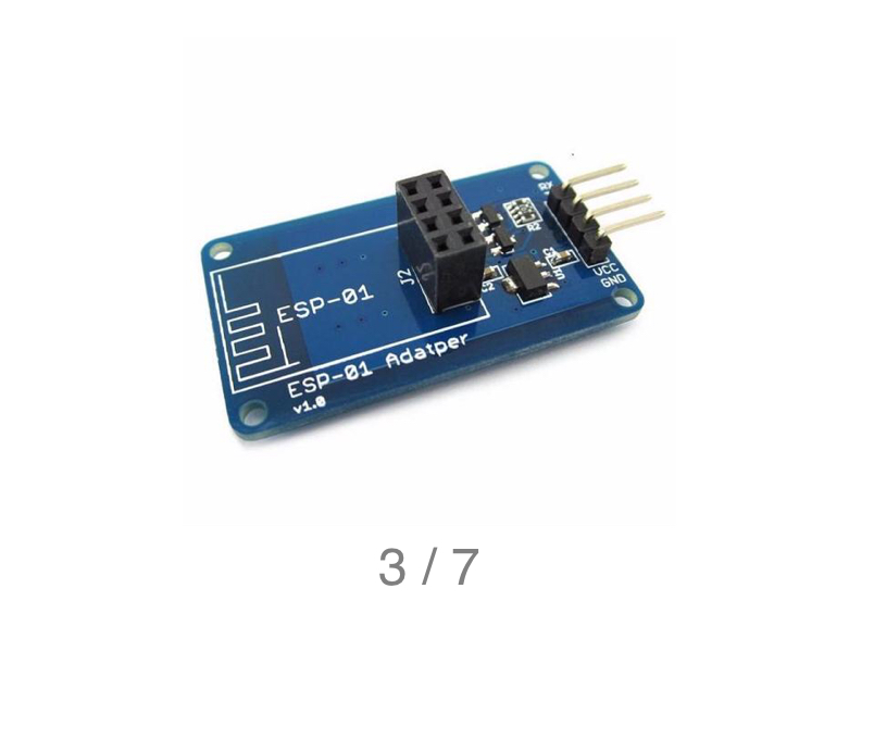
This is adapter used for flashing. Is there any particular reason why you would use it for any other purpose? ? And why not using ‘regular’ GPIO0 and GPIO2?
I have some and they don’t appear to be able to do anything other than flash a new sketch, without modification.
I’m powering it from a 5v usb style phone backup battery so I’m using the adapter for converting 5v to 3.3. Since the adapter only brings out RX and TX lines and not gpio0 or gpio2, I was just going to use one of those. And I want to use the output to drive a WS2812B addressable led strip that operates on 5v.
Why not use a real ESP?
1 Like
Haha!  This is what I have at the moment.
It will work fine with 3.3V logic. And WS2812 will work on 3.3V Vin as well. But I fully agree with Costas, you should look for NodeMCU or Wemos Mini D1.
Z,
I’ve read on other websites that it’s boarderline according to the data sheet of the ws2812b and you could have issues at 3.3 volts. I realize the adapter was only built for flashing. But I don’t see any reason why the logic level converter that’s built into the ESP adapter wouldn’t work to get back to a 5v level. Do any of you? And then it sounds like I would just have to use GPIO1 or GPIO3. Correct?
If the level converting circuit is not built as bidirectional, then it may not work as expected, or at all.
But all that aside… I am still waiting for a Blynk related question ![]()
ESP GPIO’s are 5V tolerant. So if you have 5V at input, nothing bad will happen. But GPIO will not give output more than 3.3V without llc… I’m telling you from practical experience that ws2812b is working with 3.3V Vin and 3.3V logic. So I think that solves your dilemma. Regarding GPIO1 and GPIO3, you can use them without any problems, just expect little chatter while boot on TX. There is no way to avoid it.
And yes, we got carried away, how is this Blynk related topic? It seems Blynk became reputable ESP community after all
It’s not directly related to Blynk but quite important to some Blynkers, so a valid subject in my book ![]()
Teo, my “mate” at Espressif has said his MCU’s are 5V tolerant and our tests seem to confirm this but it’s unclear if he was referring to real ESP’s like the 12 or the original “tester” 01.
Gunner,
My project is connected to Blynk with OTA update functionality. But I suppose yes this is more of an ESP related question. I just figured someone on this board would have experience at using RX and TX pins after freeing them up with OTA functionality.
Every ESP is 5V tolerant. I left one of mine esp01 four days working on 5,12V Vin. It’s still alive and kicking. Then I thought I got HT7333 with my whiteboards for ESP07, but it was in fact AMS7111. So five of the modules were working for days on 4,17V Vin, and one of them is still in everyday use some 3 weeks after I discovered why led’s on my new modules are brighter than usual ![]()
This is significantly lower than 5V.
I have run some of my ESP-12’s for months on 5V with no “apparent” ill effect.
I don’t think I have ever read a post where an ESP user has blown their chip at 5V.
Up to each individual to decide. My view, if you have lots of them go with 5V, if you only have 1 stick to 3.3V.
2 Likes
My truck is parked in my yard, but I don’t ask the landlord vehicle maintenance questions ![]()
Regardless, as @Costas said, it is important (ESP’s being the defacto standard MCU for Blynk) … So, ESP GPIO 5v Tolerance (as long as powered via 3.3v) seems “official”… or simply a way of selling more ![]()

But as for using the TX/RX pins as normal GPIO… have you tried it yet? or just asking first. I can’t afford to replace mine so I am not about to test it yet ![]()
There appears to be a lot of info about this on the Web… have you looked at any of those?
https://www.forward.com.au/pfod/ESP8266/GPIOpins/ESP8266_01_pin_magic.html
ESP01 with 3 Pinouts needed - Everything ESP8266 ← This one seems promising for at least the one port GPIO 3 (Rx)