Which firmware for the ESP-01 is needed to use Blynk with Arduino IDE?
I always thought that it is like any other ESP8266 board (just not as convenient)… As long as you have the latest ESP core installed in your IDE and the ESP-01 properly wired and connected (the inconvenient part) to the PC i.e. via a TTL-serial adapter, then you just flash it with your desired Blynk sketch and it starts working.
It hasn’t been working for me, I get this error:
error: espcomm_upload_mem failed
I have programmed at least one of these ESP-01s before. I got them from Addicore:
https://www.addicore.com/ESP8266-ESP-01-p/130.htm
I am using this programming adapter which I have 2 of:
https://www.amazon.com/ESP8266-ESP-01-Programming-Development-Auto-reset/dp/B01DS24VG0
The error message is the same with both programmers. I am using an Adafruit FTDI cable that works with other boards.
I am using the following settings on the Arduino IDE:
Board: Generic ESP8266 Module
Flash Mode: DIO
Flash Size: 1M / 64k
Debug Port: Disabled
Debug Level: None
Reset Method: ck
Flash Frequency: 40MHz
CPU Frequency: 80MHz
Upload Speed: 115200
Port: COM4
Programmer:  AVRISP mkII
For 2 of the ESPs the red and blue leds are on steady. For the third the red is on steady but the blue is flashing ~ once per second.
A very strange thing is happening for the 2 that have steady on blue leds, if I plug them in, the mouse cursor, in windows, jumps to the right about 3 inches every second or so making it impossible to do anything with them.
Well, this is the Blynk forum… sounds like you need to sign up over at ESP8266 Community Forum · GitHub as well.
https://www.google.ca/search?q=error%3A+espcomm_upload_mem+failed
Red is power Blue is link, TX, RX, or just because it looks perdy (probably link - flashes every time some communication happens)
Yep, a question for the ESP forum… probably something to do with whatever firmware is loaded and how it is affecting the serial connection.
So what firmware is needed to use all of the Arduino libraries ?
At Expressif there seems to be several versions of firmware
NONOS SDK
RTOS SDK
IOT Platform
AT BIN
I don’t know at these are. I just want the normal regular version that everyone uses with the Arduino IDE to use standard Arduino libraries.
I thought I would try to re-flash them with the flash tool and maybe they will be fixed then.
Dude… Got Google?
The “firmware” is whatever sketch you load in…
Want a blinky LED, load in the blink.ino and hook up an LED to one of the 2 available GPIO pins.
https://create.arduino.cc/projecthub/ROBINTHOMAS/programming-esp8266-esp-01-with-arduino-011389
Want basic Blynk control over all two GPIO pins, load in Blynk Blink
If you want to go back to the AT firmware (used when turning the ESP-01 into a simple WiFi to Serial adapter) then look for whatever one floats yer boat.
http://help.blynk.cc/how-to-connect-different-hardware-with-blynk/arduino/esp8266-with-at-firmware
The message you get when you try to upload your code to the ESP looks like the sort of error you get when the ESP isn’t in programming mode. This is one of the things that makes these devices such a pain. They don’t have a button to press when powering-up to put them in bootloader (programming) mode. Instead you have to connect them up in a different way when you want to flash the firmware.
The issue with the mouse jumping around sounds like a USB driver problem.
As far as ‘what firmware do I need’, you’re writing your own code in the Arduino IDE then compiling it into a new fie ware package and (hopefully) uploading it. If you uploaded one of the standard firmware files then it would overwrite the Blynk code that you’ve written.
Pete.
1 Like
Ya, that article (and the ESP forum) I passed on explains that and what to do to program it… Thank heavens for Google ![]()
1 Like
FYI I spent several hours today googling things. I found discussions about updating the firmware, I didn’t understand that when you compile sketches using Arduino IDE it includes everything.
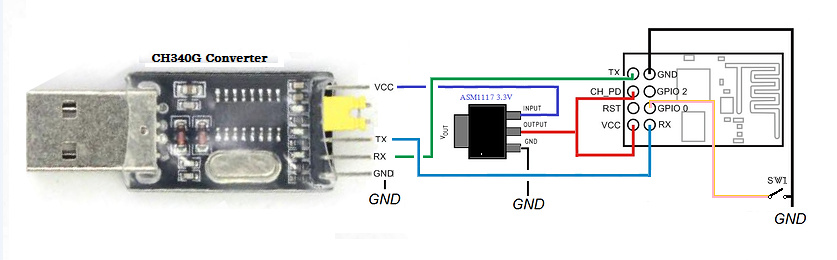
In my previous post I put a link to the programmer board I am using. It uses the DTR signal from the FTDI cable to reset the ESP and there is a button which grounds GPIO0 for programming.
https://www.amazon.com/ESP8266-ESP-01-Programming-Development-Auto-reset/dp/B01DS24VG0
So I will try to restore the original firmware with an independent Flasher program since I can’t seem to do anything with these with the Arduino IDE. I don’t know what happened, the last time I used them was a few years ago.
FYI I am interested in the -01 because I was going to use a lot of them to run WS2812B leds at several locations around the house as Christmas lights and inexpensive is attractive.
Typing firmware into the Help Center search will bring up that (as of yet unclicked) link I provided above… might have helped you understand how it (flashing ‘basic aka AT’ firmware) works a bit quicker.
Same here ![]() Spent my laundry budget for the month and am waiting for one, with adapter, to eventually show up from China…
Spent my laundry budget for the month and am waiting for one, with adapter, to eventually show up from China…
wow, DON’T DO THAT! ![]()
![]()
![]()
 Priorities or stink pretty… my cat don’t care and I wants Moar ESP
but what if you have to meet someone???
The other thing to try is flashing the firmware in DOUT mode rather than DIO in the Arduino IDE.
Pete.
That never happens… introverted geek but I do have emergency backup clothing and a shower… just have to move all my electronics out of it first I guess… hmmm… nope… (bolt locks door  )
)
2 Likes
Well I found out a few things FYI - on both programmer boards the programming button is not connected to ground so nothing happens when you press it, the boards are defective. I programmed 2 of the ESP-01s using the programmer board with a manual GPIO0 button. The other programmer board will not program even with the manual GPIO0 button. Refund requested! The third ESP-01 won’t program with either programmer. Might try to flash AT firmware later.
@psoro, actually, the voltage regulator is not needed. the programming board can supply enough juice for the esp. i have programmed and tested sucessfully at least 40 sonoff with the vcc from the programmer.
just solder together the vcc and 3.3v pins on the pcb to discard the jumper and gain access to the vcc pin with a jumper wire
@perigalacticon, please do not buy esp-01 boards anymore, they are obsolete and have low memory. use esp-12 series instead.