Wow, do you have your epever connected directly to a raspberry pi? Thats awesome! I was thinking of a round about way to use esp12 and send mqtt messages to the pi. But I can see that we can route the ethernet wire directly and and use this converted and connect it to the pi’s usb. Can you share the driver and code that you have used?
Hi Jamin,
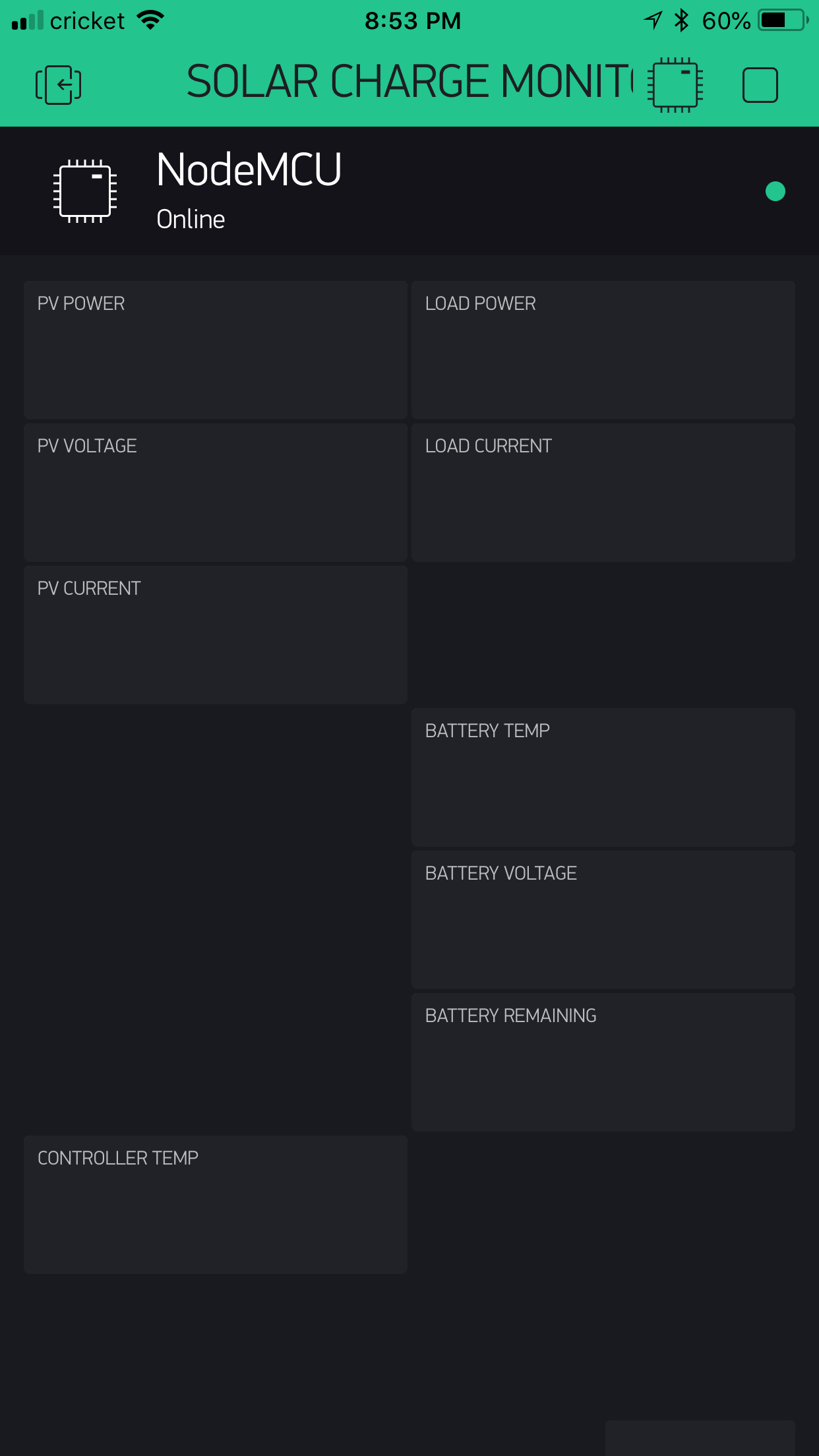
I’m following your instruction to program the ESP8266 mini, everything went smooth. On the Blynk app, the NodeMCU is online but nothing display on screen .
Would you please help me and let me know what I did wrong or am I missing something?
Hi All, I got some conflicts in compiling the Github .ino file. Someone can help me in finding the way ?
I report the errors:
In file included from C:\Users\RPRO01\AppData\Local\Arduino15\packages\esp8266\hardware\esp8266\2.4.0-rc2\libraries\ArduinoOTA\ArduinoOTA.cpp:13:0:
C:\Users\RPRO01\AppData\Local\Arduino15\packages\esp8266\hardware\esp8266\2.4.0-rc2/tools/sdk/include/user_interface.h:657:174: error: declaration of C function ‘int wifi_send_pkt_freedom(uint8**, int, bool)’ conflicts with
int wifi_register_send_pkt_freedom_cb(freedom_outside_cb_t cb); void wifi_unregister_send_pkt_freedom__cb(void); int wifi_send_pkt_freedom(uint8 **buf, int len, bool sys_seq);
^
In file included from C:\Users\RPRO01\AppData\Local\Arduino15\packages\esp8266\hardware\esp8266\2.4.0-rc2\libraries\ArduinoOTA\ArduinoOTA.cpp:13:0:
C:\Users\RPRO01\AppData\Local\Arduino15\packages\esp8266\hardware\esp8266\2.4.0-rc2/tools/sdk/include/user_interface.h:537:5: error: previous declaration ‘int wifi_send_pkt_freedom(uint8*, int, bool)’ here
int wifi_send_pkt_freedom(uint8 *buf, int len, bool sys_seq);
^
exit status 1
Error compiling for board Generic ESP8266 Module.
I’ve been trying for about a week to get this working. I have the EPEver Triron 4210 Charge Controller and I’m using a Raspberry Pi 3. I’m using pins GPIO14(TX), GPIO15(RX), and ground to connect directly to the controller through Ethernet cable. I can’t seem to get this working no matter what I do. Can you lend a hand? I also noticed that there’s a library named MODBUSMASTER I can’t find nowhere, and the ones on Github don’t seem right.
Hmm. Well you’ll definitely need the modbus library:
Or “pip install pymodbus”
And here’s some barebones code to test with:
#!/usr/bin/python

from pymodbus.client.sync import ModbusSerialClient as ModbusClient

modbus_timeout = .1 # NOTE! This is default 3 seconds. It waits for the timeout before returning I think. Making this .1 works well. The pyepsolar project uses a 1 second timeout.

client = ModbusClient(method = 'rtu', port = '/dev/ttyUSB0', baudrate = 115200, timeout=1)
client.connect()

result = client.read_input_registers(0x3100,6,unit=1)
solarVoltage = float(result.registers[0] / 100.0)
solarCurrent = float(result.registers[1] / 100.0)
batteryVoltage = float(result.registers[4] / 100.0)
chargeCurrent = float(result.registers[5] / 100.0)

print solarVoltage
print solarCurrent
print batteryVoltage
print chargeCurrent

client.close()
On a sidenote I found the Tracer controller to be very sensitive to grounding issues. Mine would periodically stop responding. Although, oddly, it would always work with the MT50 remote monitoring box, which I think uses the same protocol. I’d solve it for awhile and it would work well, and then just stop responding for awhile. My system was a bit odd though, I have 900 watts of panels and I’m running a propane/ac fridge off AC sometimes (my Pi kicks the fridge over to AC when my 4 Trojan T105 batteries are fully charged). I don’t know if that was a factor.
Eventually someone gave me a very used but still working Morningstar MPPT60 charge controller so I shifted over to that, which has been pretty rock solid. But oof those things are pricey.
Thanks so much. So, to be clear: I can just virtual write the results by inserting the python code right into the Blynk code (I’m assuming blink code = python). Sorry for being so N00b, but I’m just getting into this Raspberry Pi world (always been a C++/Object Pascal fanatic)
import time
import os
from pymodbus.client.sync import ModbusSerialClient as ModbusClient
modbus_timeout = .1
client = ModbusClient(method = ‘rtu’,port = ‘/dev/ttyUSB0’,baudrate = 115200, timeout=1)
Finally sending values to the virtual ports. Thanks for your help. Now I need to refresh that data every 30 seconds or so, but once Blynk starts, I can’t send that data. Any thoughts?