The COM port is RS-485 half-duplex communication. There is PC software and also a small remote controller called an MT-50. There is also a Branded Wifi module you can buy which will let you run the software on a remote computer. Still not really good enough for someone like myself who would rather have the info in their pocket.
I borrowed some starting code from the only person on the internet who documented anything to do with the Tracer A-series (RS-485) communication and Arduino. After reaching out he gave me his working code. From there it only took 2 hours to convert it to Blynk.
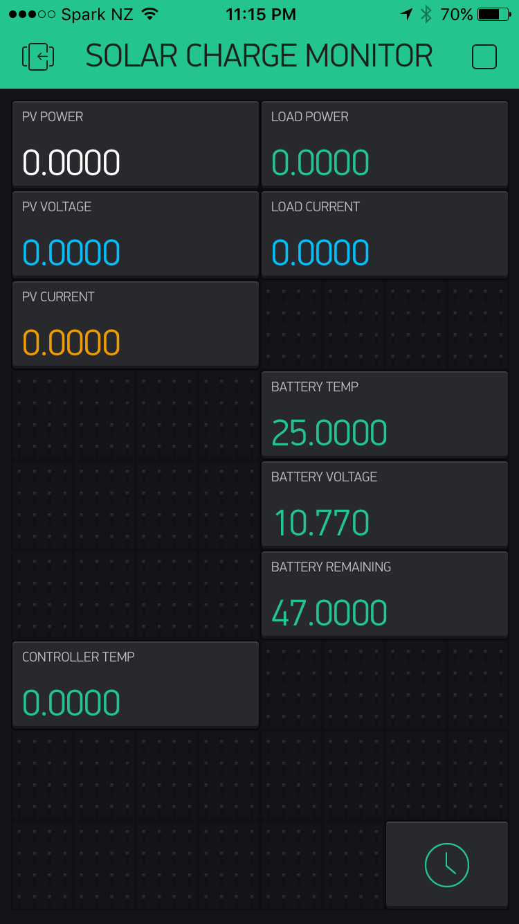
Its only very basic, but it works.
Some things I wasn’t told…
You can only read the Modbus register ever 500ms… It took a long time to find a way to cycle through just 2 registers but I got it working by cycling to the next function every 500ms.
The code is below. Its still a major work in progress but maybe someone out there would want to develop with me. Just make a pull request on Github.
Lots of 0.000’s because I only have a battery hooked up.
Hi - I attempted to get the code but the github gives me a 404 error. Do you have an updated github?
I am wanting to give this a try with a Tracer 2215BN. It uses the MT50 so I would think it would work, maybe the target data is in a different location but should be very similar or maybe even the same.
Looking at some of your projects they are similar things I am working on. I live in Alaska, off the grid so solar/wind is key to me. I am working on a automated greenhouse with some water control (transfer, measuring irrigation, etc).
Take care and thanks for sharing the project.
Glenn
The RN model should work as it also uses RS-485… the older Tracers use RS-232.
Just note that I currently am waiting for my Tracer to arrive back from China after being repaired and that the code was developed in only 1 day before I broke it… lol
so right now it only sends back very basic info… you’re welcome to help develop it while I wait for my new unit to arrive
Ben - thanks for the update and the info. I just ordered a UART to RS485 adapter from China so we will see if your controller or my adapter comes first. As I develop code I will share it with you. You can incorp or not as you see fit.
Cool project! I’m trying to communicate with a Tracer 4210a and it mostly works, except that the Modbus interface stops responding periodically for hours on end.
Have you ever run into that issue?
And I’m curious about this observation:
What happens when you try? Does it crash or just not respond?
I’m reading multiple addresses at once, and I wonder if that could be my issue. This is the stripped down Python code I’m using from a Pi:
#!/usr/bin/python

from pymodbus.client.sync import ModbusSerialClient as ModbusClient

import time

port = "/dev/ttyUSB0"

client = ModbusClient(method = 'rtu', port = port, baudrate = 115200)
client.connect()

while True:


    # read 6 registers starting at 0x3000
    result = client.read_input_registers(0x3000, 1, unit=1)

    pvVolts = float(result.registers[0] / 100.0)
    pvAmps = float(result.registers[1] / 100.0)
    batteryVolts = float(result.registers[4] / 100.0)
    batteryAmps = float(result.registers[5] / 100.0)


    print "pvvolts=", pvVolts
    print "pvamps=", pvAmps
    print "batteryvolts=", batteryVolts
    print "pvcurrent=", batteryAmps
    print


    time.sleep(1) # pause before reading the next register

    # read the battery SOC
    result = client.read_input_registers(0x311A, 1, unit=1)
    batterySOC = result.registers[0]

    print "batterySOC=", batterySOC
This works well for awhile, and then will start have connection issues seemingly randomly. If I read the batterySOC (the second register reading) it seems to have issues more frequently.
It’s driving me nuts!
I’m trying to make it so the fridge in my RV runs off electricity when the battery is full (the SOC is > 95%) and the panels are putting out more than X watts. Its all running beautifully and my Pi flips a relay that makes the fridge run on electricity for awhile, which saves a lot of propane, but then the whole thing will stop working for a day. Ugh.
I wrote some more on it here:
And here’s someone else communicating with a Tracer controller:
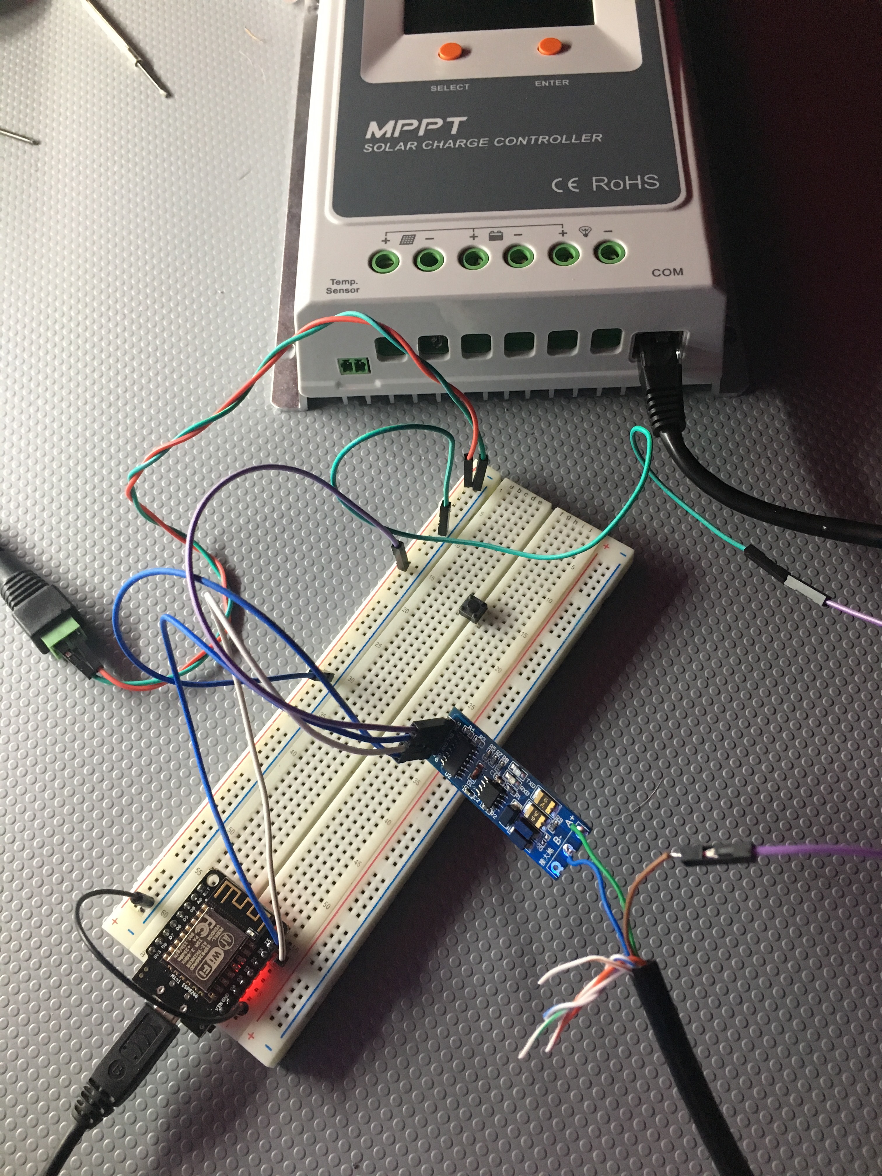
I’m currently trying to read the data from the back of the MT50 remote monitoring box from an Arduino.
Unfortunately during the first packdown, I broke a terminal block resulting in a the battery ground wire getting stuck, so I just didnt have the time to test for long. I worked on the project for about 2-3 hours on a Saturday morning and had taken the unit back to the post office by Sunday to send back to China.
I can’t quite remember, but I think I was getting null data back if I tried to query a register quicker than 500ms. I couldn’t explain it so most of the final 2 hours was spent working out the issue.
As soon as my refurbished unit arrives, I will be diving right in to this again!
Also thank you for posting those links! I hadn’t seen the uk site!
Great, I’d love to hear how it goes. I’m rewriting my script now so it just reads one register at a time (instead of 6 registers in a single reading), hopefully that’s it! Its been really hard to troubleshoot since it sometimes takes 6 hours for the issue to appear.
I’d really like to get this going on my set up.
I would like a link to the
github, “modbusmaster library”
used here, as I seem to find several versions, maybe they are all the same? Not sure. But it would help me to start at the beginning with all things being equal.
UPDATE
I went with this one
Seems to work fine.
I’d appreciate some pointers how to isolate bits
D3-2: Charging status. 00 No charging,01 Float,02
Boost,03 Equlization
on address 3201,
I’m new to arduino, and a lot of the fun is in the exploring, but sometimes, a pointer in the right direction can help.
I am setting up solar panels on a sailboat with a 3215BN. When I am at dock, I use a dc power supply on the PV input. It is easy this way, no need of a battery charger. Since at dock there is power 24/7, I want to use a lower voltage for float charging to save the battery. Eventually I will use LiFepo4 bank also. So when I get power fron the psu, I need to send from esp8266 or else a new value to the CC for float voltage every time I dock in-out. This is my project, just beginning and not much skills in coding… lots of fun to come !!! I will pick into your code guys !!
I set the delay to 1.1 seconds, and still have the same issue of the controller randomly becoming unresponsive for hours at a time, especially during times of high solar output.
I’m wondering if it’s a grounding issue. I’m using this adaptor:
I used to get time outs on my set up, A Tracer3215BN, and the usb converter that came with it, using Solar Station Monitor from EPever…
I noticed it only happened when the inverter was on. I have seperated the cables as much as possible, certainly never touching. I also went for a CAT6a, I needed a 15M run.
I have not experienced the problem since. Guess it could have been electrical noise/interferrence.
I started to use my Arduino in earnest, to read my tracer recently, and also found I had lost data, even with my CAT6 cable! Changed the code as below, It reads the register about four times if it gets a 0 response meaning no register read. This has provided about 99% success. The first delay is to give the tracer a moment to settle down, the second one ensures we don’t stay there forever. As you can see it’s to get the status of the tracer. I guess I could make the delay longer if need be. I’m a novice at this coding, so if there are gaping faults, please let me know.
 //void AddressRegistry_3201() ????????????? Charging Status (Read Only)
 //D3-D2 00=No charge, 01/1=Float, 10/2=Boost, 11/3=Equalisation
 started_waiting_at = millis();  //Get start time
result = Tracer_modbus.readInputRegisters(0x3201, 1);
while (!result == 0) {
 delay(50); // give tracer a moment to settle down
result = Tracer_modbus.readInputRegisters(0x3201, 1);
if (millis() - started_waiting_at > 220 ) { // but, if we have waited 220 mls move on.. se how this goes
  //Serial.println("No response received - timeout!");
  break;// and get out of this while loop, otherwise we could be here for ever.
}
}
 if (result == Tracer_modbus.ku8MBSuccess)
{
ChrgStatus = Tracer_modbus.getResponseBuffer(0x00);
ChrgStatus = ChrgStatus >> 2;// shift right 2 places to get bits D3 D2 into D1 D0
ChrgStatus = ChrgStatus & 3; // and it, bit wise with, 0000000000000011, to get just D1 D0, loose th rest
Serial.print(ChrgStatus);
Serial.print(",");
}
  else
{
rs485DataReceived = false;
//Serial.println("Fail readInputRegisters(0x3201, 1) ");//take this out later
Serial.print("66.66,");
}
hi I’m Karthik from India. and I’m new to this Arduino.
I would like to clear one doubt which is somehow closely related to this.
Is it possible the read the rs485 burst data using Arduino?
Well, after troubleshooting this for ages, I finally solved the problem of losing contact with my Tracer 4210a when the sun got high. To recap, the charge controller would stop responding over modbus whenever it was charging above 400 watts or so (I have 600 watts of panels connected to it). And the solution is…
grounding of course.
Can’t believe I didn’t think of it sooner.
Anyway, grounding the modbus cable coming from the charge controller to one of the GPIO ground pins on the Raspberry Pi solved it. That’s pin 7 or 8 from this diagram: