i know it’s not exclusive and all about Blynk but i would happy to know your opinion
introduction.
as a new maker (5 months ) I just started using Arduino UNO and a breadboard but after that i know the limitation of that specially in connecting it to other thing. after that I start to see ESP8266 blowing everything else with very high potential and ideas. but ESP8266 is not breadboard friendly (before NodeMcu and Wemos D1/D1 mini shows up) and even if you create your own adapter you have to connect to many resistors and pull-up and Pull-down many pins to get the board in boot mode or flashing mode. even after that you will have many jumper wires and even with prototype board and soldering you will either have a big size board or clunky wires.
the Idea
as I start playing with Arduino and ESP8266 MCU I immediately think why not to use it to switch things on/off and what about control LED lights also so , I started that on breadboard and it’s working , but again to much jumpers wires and endless issue because of the moving wires , and to do it in prototype board with a lot of soldering work and time it works fine but not looks like something I can use it in-wall electricity box so I start learning how to transfer my project from breadboard to PCB.
From prototype board to PCB
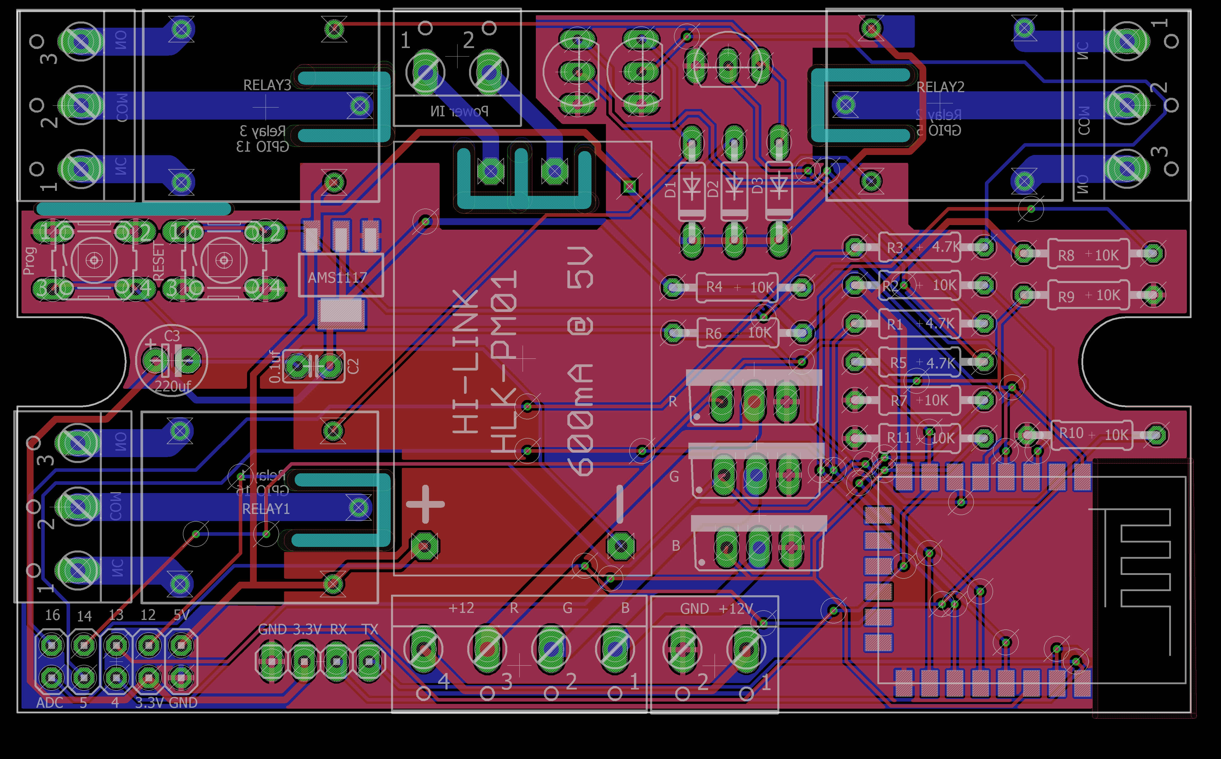
Learning EAGLE CAD for PCB layout and schematics , reading too many Datasheets of parts that I need to use it in my board like MOSFETs , Transistors , Relays etc. That takes me a lot of time and what I like that I learn a lot of things here that I will never know if I didn’t go that farther in electronics. I designed the schematic and also Layout in EAGLE but because I live in Saudi Arabia – but I’m Egyptian – and all the parts and PCB has to be imported as I will never find a PCB Manufacturer or a Parts supplier here so any mistake will takes me along time and additional cost to re-manufacture the PCB and source the parts again. So I show my design in www.esp8266.com to get help in my schematic if any mistake or wrong part used and I can’t describe how these guys helped me out to get the schematic With almost no error. Here I must thank the martinayotte and AdrianM from www.esp8266.com they helped me a lot to fix some mistakes in my
What that board will do.
PCB size : 92X55 mm that will fit in-wall electricity box MCU : ESP8266/ESP-12F power:
Built in power supply AC/DC 5V@0.6A
3.3V regulator for ESP-12F
12V power input for LED strip
Relays: 3 relay 10A (advised to useit up to 3A max). LED strip : 3 channel - RGB - LED strip supported(advised 3A max per channel). GPIOs all the GPIOs is broken to a male header if you want to use it for a different purpose.
Disclaimer
I accept no responsibility for any damage caused through following advice in these pages. When dealing with mains voltages.Please take some professional electronic designer before to use any of my designs or advises as I am totally Hobbyist just doing this for Fun.
Man please don’t use through hole components this board can be 1/2 the size:P Anyway awesome job for the beginner. Lastly I would separate power supply from the board but that’s your call, most likely your solution wil make many people happy cause it’s idiot proof plug it and it turns on.
Dude this is amazing! After 5 months of tinkering all I had to show for it was hot snot on a perf board! Interested as well to know where pricing ends up.
hi @Pavlo
i missed to mention the Board size , i updated the details and it’s 92X55 mm
i was designing it for my personal use in my new apartment.
also i do my best in the design to make it safer to use be this still rev. 1.
do you think many people will be willing to purchase it?
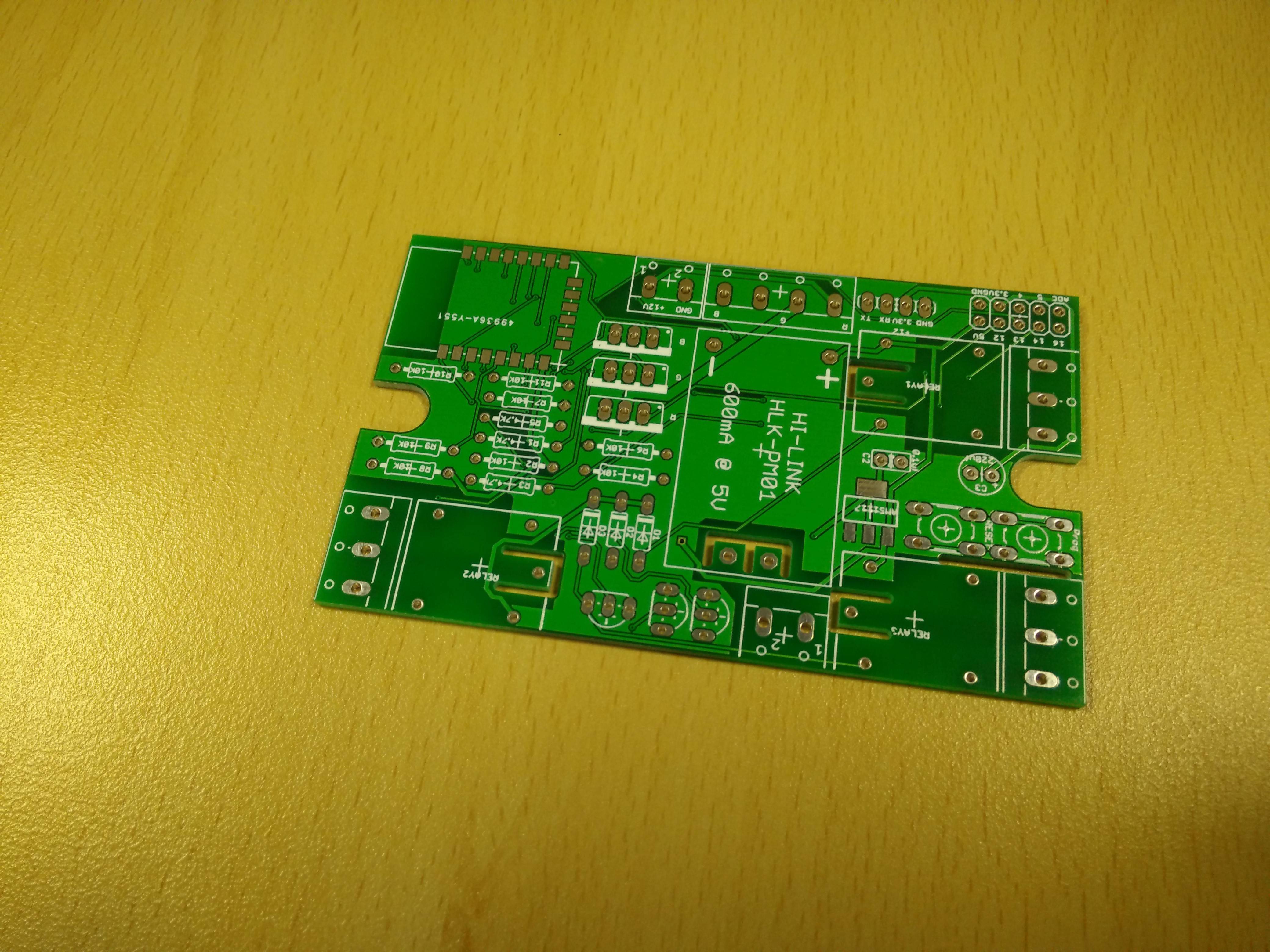
@conkerkh i have used THD because i was just testing my soldering skills and that can be an easy kit also for beginners like me.
and i used the supply in same PCB to save size as my initial plan that all of the project need to be fitted in a normal wall electricity box.
and that is easy an simple to me to program it using USB to serial and later OTA after it’s fitted in the wall.
using Arduino IDE or my new favorite IDE Platformio
I love the wiring on the bottom of the board I do the same sometimes😜 And small advice for the future, you should move all the HV AC lines on one side and separate it from LV you can easily fit 3 relays on one side. Lastly decouple RST pin because you might encounter some unexpected resets.
my design used a some of expensive parts like the power supply and ,and parts with PCB with shipping of parts from multiple places (register mail not express) go almost $22.
i just make a small patch of 10 Boards , but some of the parts are sold with minimum of 50 or 100 Pcs.
that not includes the time to understand all that parts and selecting the proper MOSFET that will not overheat , learning EAGLE CAD and designing the PCB layout.
the final developing time takes me almost 2 months (my spare time of 10 hours job 6 days a week) , as i have no change to re-fabricate the board one more time or get the wrong parts.
i have change the layout many time to reach this and the problem is that i have big parts like the power supply and the relays that , and even with SMD parts only resistors and the three diodes can be SMD
and also that will not save much space as you need to keep a space to route your wires
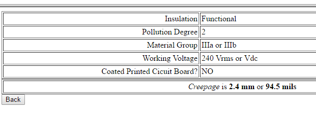
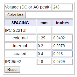
In many cases you are routing High Voltage AC lines over, under or close to LowVoltage signal lines. It totally doesn’t seem right to me as far as I know on all power supplies there is clear separation between AC and DC and low voltage high voltage in your case there isn’t you have 240V going through your board think about it. Doing LV board is not an issue as it wont electrocute you. In your case you need to think of safety… Apart from this it’s really good job for first time so congrats!
the one worry as people mentione is having AC in the middle of the board, but if the slots are milled and the distance is enough, that might not be a cocnern. You might want to test isolation at some point, i ve seen it tested with 2500 and 5000v to be sure it’s save on wall chargers for instance and many failed.
Also as protection, in other devices i’ve seen a fuse and a varisor added on the AC side of things. I am no electrical engineer but people seemed to think they were very important to not burning down your house
my version of something similar so so primitive, perfboard and off the shelf relay board, that i m now ashamed even to mention it
great job
/edit you’ve also mentioned it’s not exclusive to blynk, but, after playing with a lot of other stuff, i really can t see what you d use to control it easier
@tzapulica this is my first time ever to make PCB , i have tested and it’s working.
a good point you mentioned is to test the isolation , unfortunately i have no access to such equipment but i will look where i can just do these test.
and again i can refine the PCB design to avoid the traces near the AC lines.
it is can be used with any solution not only Blynk as it is just ESP8266 board. , and Who can come up with something easier than Blynk , i usually use Blynk with your Node-red Websocket node.