Only when you have the flame and LED’s off with no flame, right?
No, though the fire is off, the LED is on. Otherwise, when the fire is on, the LED is also on.
That is not right, you might need to adjust the trim pot so no flame no LED, with flame LED comes on.
Serial ports can only connect to one device at a time.
When I said use Termite, I meant with a TTL-USB adapter running on a different COM port on your PC and grabbing data from a different Serial command in the sketch (on an UNO, you would use Softserial port for debug/monitor).
@Maria I am new to these Wemos boards, but I have noticed a few things…
The pin choices are very picky, some pins are used when booting: D0 for sure, and may cause issues depending on what you have wired to it at bootup.
Some are wired as internal pullup: D3, D4, D8
And the Analog pin A0 can only take 1v input! (EDIT - actualy 3.2v/3.3v on Wemos Mini, see below) Feeding in a 3.3v signal may, at worst, kill the port, or at best, always read as HIGH. But you can put a 100k resistor inline, and that should work in conjunction with the internal divider to drop your 3.3v signal to the required 1v input.
So why a 100k resistor? See reference to that in here:
The WeMos already has resistors and can take 3.2V (technically not 3.3V).
Oops, correct… I haven’t played with that circuit yet, so the details are not firm in my mind ![]()
Yes, in that Battery Monitor case, the extra resistor is only necessary for the batteries full potential of 4.2v.
But if that sensor was powered by 5v (assuming it is not working correctly on 3.3v), then its signal would also be 5v and thus using the similar inline resistor method might be required… it would need a higher resistor then 100k, but I can’t do the math to calculate that ![]()
The 220K R1 used by WeMos needs to be increased to at least 400K to cover 5V.
https://www.daycounter.com/Calculators/Voltage-Divider-Calculator.phtml
Thank heavens for calculators 
Yes, so taking the existing 220k (and 100k) built into the Wemos… for a 5v input, one would need to place an additional 180k resistor inline with the signal.
Yes and assuming you only have 220K available, like WeMos and I, the total of 440K will give protection to 5.4V.
And of course, the higher the resistance added, then not only higher the tolerance allowed, one must also account for that potential increase in the calculation of the analog readings, else the data will be off… Programming and electronics combined make math challenged people cry 
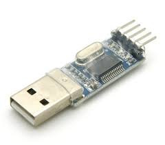
Sorry, I have forgot that usb-ttl. But, I tried use usb-ttl and always error uploading to board. Btw, I use arduino uno which use chip CH340 and usb-ttl CH340. Is the board can’t usb-ttl or what?
A TTL-USB adapter is a separate cable like device…
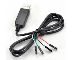
By plugging one into the UNO with SoftwareSerial (e.g. pins 10/11 or 2/3, etc) then you get TWO serial connections; The primary one for Programming & Blynk Server connection and the 2nd (the TTL-USB) for Serial Monitor with Termite.
If wemos have resistor 220k built in it, then I have to add resistor amount 427k, right? Why the total become 440k?
Means the usb cable still used, isn’t it?
It has a voltage divider of 220K R1and 100K R2. So by adding 220K to the 220K you have a total divider of 440K R1 and 100K R2. This is a ratio of 4.4 : 1. So the initial 1V becomes 1V + 4.4V = 5.4V.
See schematic https://wiki.wemos.cc/_media/products:d1:mini_new_v2_2_0.pdf
Not with the WeMos.
Yes, I mean if I use arduino uno with usb-ttl, the usb cable still used right?
Sorry to confuse you… @Costas and myself were just having a discussion back and forth about the overall totals and values.
If you are powering your flame sensor on 3.3v then you shouldn’t need any resistor between the sensor and the A0 pin.
However if you are powering the sensor with 5v, then you should have a 180K resistor inline with the sensor and the A0 pin. I don’t know if this sensor simply detects the flame or can also determine the “amount” or intensity of the flame.
If all you need is a binary HIGH/LOW, then you simply need to make sure that the resistor is large enough to protect the A0 pin from seeing more than it’s rated 3.3v maximum limit.
If however you have a 0v-5v signal and you want to precisely scale it’s range, then you need to keep the resistor at 180K, since if you go with a higher value resistor, then you can account for the change with calibration, but will lose some resolution.
That is correct.