Version 0.7 with bug fixes.
Thanks to @Costas big help and contribution !
Next version I will try to improve the quality of my sketch using functions for the “repeated” code…
#define Version "0.7"
#define WellcomeLine1 " Mike Kranidis "
#define WellcomeLine2 "release Ver="
#define WellcomeLine3 "RF Remote ELRO AB440, with outlet 'sync' status, Full OTA"
/// ELRO AB440R (system code DIP switches 1 to 5 set as ON-OFF-ON-OFF-ON) ///
/// see https://github.com/sui77/rc-switch/ ///
/// associated with: Client Name: ESP_CED95B / MAC Address: 18:FE:34:CE:D9:5B ///
/// Blynk related setup ///
/*
* ALL ZONES OFF V0
*
* ALL ZONES ON V10
*
* ZONE A - ON/OFF V1
*
* ZONE B - ON/OFF V2
*
* ZONE C - ON/OFF V3
*
* ZONE D - ON/OFF V4
*
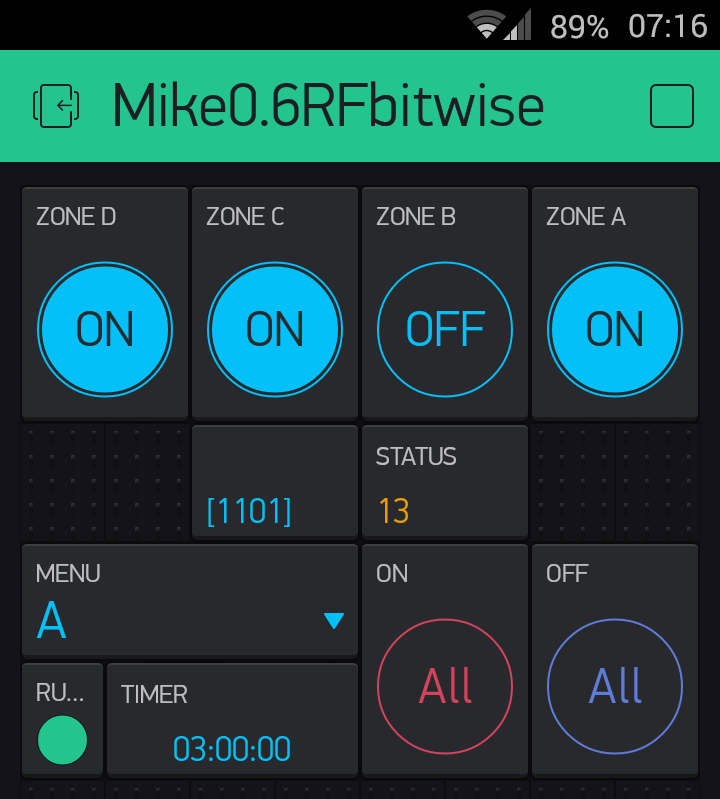
* V14 outletsStatus integer variable that keeps the status of 4 outlets in bit wise operation bit0 <-> outletA bit1 <-> outletB bit2 <-> outletC bit3 <-> outletD
*
* V15 outlet select menu
*
* V16 timer
*
* V20 switch to activate ArduinoOTA.handle() on demand
*
* LED V21 led0 RUN? virtual LED
*/
/// mapping the syscode of the RF Switch system as well as outlets A - E ///
#define syscode "10101"
#define outletA "10000"
#define outletB "01000"
#define outletC "00100"
#define outletD "00010"
#define outletE "00001"
/// RF Transmitter is connected to WeMos Pin #D0 but can be changed here ///
#define WeMosPin D0
/// internal WeMos LED pin #D4 ///
#include <ESP8266WiFi.h>
/// OTA dependencies ///
#include <ESP8266mDNS.h>
#include <WiFiUdp.h>
#include <ArduinoOTA.h>
/// WiFiManager dependencies ///
#include <DNSServer.h> //Local DNS Server used for redirecting all requests to the configuration portal
#include <ESP8266WebServer.h> //Local WebServer used to serve the configuration portal
#include <WiFiManager.h> //https://github.com/tzapu/WiFiManager WiFi Configuration Magic
/// blynk dependencies ///
#define BLYNK_PRINT Serial // Comment this out to disable prints and save space
/// it is used above /// #include <ESP8266WiFi.h>
#include <BlynkSimpleEsp8266.h>
#include <SimpleTimer.h>
/// RC Switch dependencies and declaration///
#include <RCSwitch.h>
RCSwitch mySwitch = RCSwitch();
// You should get Auth Token in the Blynk App.
// Go to the Project Settings (nut icon).
char auth[] = " PLACE YOUR AUTH CODE HERE ";
WidgetLED led0(V21);
SimpleTimer timer;
/// start of WiFiManager Global Start here... ////
WiFiManager wifiManager;
/// switch value to control if the WeMos internal led will be blinking if HIGH or not if LOW ///
boolean ledBlink = false;
/// boolean value for the last status of zones A B C D ///
boolean statusA = true; boolean statusB = true; boolean statusC = true; boolean statusD = true;
/// boolean value for let us know if timer is in use true or false ///
boolean caseStatus = false;
/// value that keeps the case number selection for suitable use in the outlet A to D distinguishing based on the outlet selection menu widget ///
unsigned int selected = 0;
/// timestamp variable to keep track of millis() unsigned long ticks = millis() / 1000; That is for debugging printings ///
unsigned long timestamp;
/// outletsStatus integer variable that keeps the status of 4 outlets in bit wise operation bit0 <-> outletA bit1 <-> outletB bit2 <-> outletC bit3 <-> outletD ///
/// we are using the lower 4 bits for easy case - switch implementation ... The Status are going to a Value Display widget using V14 virtual pin ///
unsigned int outletsStatus = 0;
/// SimpleTimer timer function, check each 5 minutes for the connection. If you lost it then it is doing ESP.reset() ///
void connCheck() {
if(!wifiManager.autoConnect("AutoConnectAP")) {
Serial.println("failed to connect and hit timeout");
delay(3000);
//reset and try again, or maybe put it to deep sleep
ESP.reset();
delay(5000);
}
}
/// START of SimpleTimer timer activating function blinkLedWidget ///
void blinkLedWidget()
{
if (led0.getValue()) {
led0.off();
///BLYNK_LOG("LED0: off");
} else {
led0.on();
///BLYNK_LOG("LED0: on");
}
/// END of SimpleTimer timer activating function blinkLedWidget ///
/// put the routine here to blink WeMos LED (D4) each ? second(s), using the "control software switch" ledBlink ///
if (ledBlink)
{int test = digitalRead(D4);
digitalWrite(D4, !test);
}
}
/// START OF SETUP ///
void setup() {
Serial.begin(115200);
Serial.println("Booting");
//WiFiManager
//Local initialization. Once its business is done, there is no need to keep it around
/// WiFiManager wifiManager;
//fetches ssid and pass from eeprom and tries to connect
//if it does not connect it starts an access point with the specified name
//here "AutoConnectAP"
//and goes into a blocking loop awaiting configuration
wifiManager.autoConnect("AutoConnectAP");
//if you get here you have connected to the WiFi
Serial.println("connected...yesss! :)");
// Port defaults to 8266
// ArduinoOTA.setPort(8266);
// Hostname defaults to esp8266-[ChipID]
// ArduinoOTA.setHostname("myesp8266");
// No authentication by default
// ArduinoOTA.setPassword((const char *)"123");
ArduinoOTA.onStart([]() {
Serial.println("Start");
});
ArduinoOTA.onEnd([]() {
Serial.println("\nEnd");
});
ArduinoOTA.onProgress([](unsigned int progress, unsigned int total) {
Serial.printf("Progress: %u%%\r", (progress / (total / 100)));
});
ArduinoOTA.onError([](ota_error_t error) {
Serial.printf("Error[%u]: ", error);
if (error == OTA_AUTH_ERROR) Serial.println("Auth Failed");
else if (error == OTA_BEGIN_ERROR) Serial.println("Begin Failed");
else if (error == OTA_CONNECT_ERROR) Serial.println("Connect Failed");
else if (error == OTA_RECEIVE_ERROR) Serial.println("Receive Failed");
else if (error == OTA_END_ERROR) Serial.println("End Failed");
});
ArduinoOTA.begin();
Serial.println("Ready");
Serial.print("IP address: ");
Serial.println(WiFi.localIP());
/// consider to use Blynk.config(auth); that is now ssid, password hard code specific ///
/// due to WiFiManager framework the bellow credentials are not needed anymore... ///
/// Blynk.begin(auth, ssid, password);
Blynk.config(auth);
while (Blynk.connect() == false) {
// Wait until connected
}
/// we ensure here that outletsStatus integer will have all the upper bits set to zero //
outletsStatus = outletsStatus & 15;
/// Transmitter is connected to "WeMosPin" that is #D0 by default and can be changed in the relevant define above ///
mySwitch.enableTransmit(WeMosPin);
// Optional set pulse length.
mySwitch.setPulseLength(320);
pinMode(BUILTIN_LED, OUTPUT); // initialize onboard LED as output
digitalWrite(BUILTIN_LED, HIGH); // dim the LED
/// start of SimpleTimer timer Functions
// Check the connection every 5 minutes. If not connected run
/// disabled temporary /// timer.setInterval(300000L, connCheck);
/// This blink LED function be called every 3 seconds
timer.setInterval(3000L, blinkLedWidget);
/// end of SimpleTimer timer Functions
}
/// END OF SETUP ///
/// start of timekeeper function return time in tenth of seconds can be called as unsigned long tempval; e.x. tempval=timekeeper(); ///
unsigned long timekeeper() {
timestamp = millis() / 100;
return timestamp;
}
/// start routine virtual button V0 ALL OFF button ///
BLYNK_WRITE(V0)
{
if (param.asInt() == true)
{
mySwitch.switchOff(syscode, outletA) ; mySwitch.switchOff(syscode, outletB) ; mySwitch.switchOff(syscode, outletC) ; mySwitch.switchOff(syscode, outletD) ;
statusA = true; statusB = true; statusC = true; statusD = true;
Blynk.virtualWrite(V1, LOW); Blynk.virtualWrite(V2, LOW); Blynk.virtualWrite(V3, LOW); Blynk.virtualWrite(V4, LOW); //state LOW or HIGH;
outletsStatus = 0;
Blynk.virtualWrite(V14, outletsStatus); /// set all bits (outletA ... outletD) to 0 ///
}
}
/// end of routine virtual button V0 ALL OFF button ///
/// start routine virtual button V10 ALL ON button ///
BLYNK_WRITE(V10)
{
if (param.asInt() == true) {
mySwitch.switchOn(syscode, outletA) ; mySwitch.switchOn(syscode, outletB) ; mySwitch.switchOn(syscode, outletC) ; mySwitch.switchOn(syscode, outletD) ;
statusA = false; statusB = false; statusC = false; statusD = false;
Blynk.virtualWrite(V1, HIGH); Blynk.virtualWrite(V2, HIGH); Blynk.virtualWrite(V3, HIGH); Blynk.virtualWrite(V4, HIGH); //state LOW or HIGH;
outletsStatus = 15;
Blynk.virtualWrite(V14, outletsStatus); /// set all bits (outletA ... outletD) to 1 ///
}
}
/// end of routine virtual button V10 ALL ON button ///
/// start routine virtual button V1 ///
BLYNK_WRITE(V1)
{
if (param.asInt() == true && statusA == true)
{
mySwitch.switchOn(syscode, outletA) ;
statusA = false;
Blynk.virtualWrite(V1, HIGH); //state LOW or HIGH
outletsStatus = outletsStatus | 1;
Blynk.virtualWrite(V14, outletsStatus); /// set bit 0 (outletA) to 1 ///
} else if (param.asInt() == true && statusA == false)
{
mySwitch.switchOff(syscode, outletA);
statusA = true;
Blynk.virtualWrite(V1, LOW); //state LOW or HIGH
outletsStatus = outletsStatus & 14;
Blynk.virtualWrite(V14, outletsStatus); /// set bit 0 (outletA) to 0 ///
}
}
/// end of routine virtual button V1 ///
/// start routine virtual button V2 ///
BLYNK_WRITE(V2)
{
if (param.asInt() == true && statusB == true)
{
mySwitch.switchOn(syscode, outletB) ;
statusB = false;
Blynk.virtualWrite(V2, HIGH); //state LOW or HIGH
outletsStatus = outletsStatus | 2;
Blynk.virtualWrite(V14, outletsStatus); /// set bit 1 (outletB) to 1 ///
} else if (param.asInt() == true && statusB == false)
{
mySwitch.switchOff(syscode, outletB);
statusB = true;
Blynk.virtualWrite(V2, LOW); //state LOW or HIGH
outletsStatus = outletsStatus & 13;
Blynk.virtualWrite(V14, outletsStatus); /// set bit 1 (outletB) to 0 ///
}
}
/// end of routine virtual button V2 ///
/// start routine virtual button V3 ///
BLYNK_WRITE(V3)
{
if (param.asInt() == true && statusC == true)
{
mySwitch.switchOn(syscode, outletC) ;
statusC = false;
Blynk.virtualWrite(V3, HIGH); //state LOW or HIGH
outletsStatus = outletsStatus | 4;
Blynk.virtualWrite(V14, outletsStatus); /// set bit 2 (outletC) to 1 ///
} else if (param.asInt() == true && statusC == false)
{
mySwitch.switchOff(syscode, outletC);
statusC = true;
Blynk.virtualWrite(V3, LOW); //state LOW or HIGH
outletsStatus = outletsStatus & 11;
Blynk.virtualWrite(V14, outletsStatus); /// set bit 2 (outletC) to 0 ///
}
}
/// end of routine virtual button V3 ///
/// start routine virtual button V4 ///
BLYNK_WRITE(V4)
{
if (param.asInt() == true && statusD == true)
{
mySwitch.switchOn(syscode, outletD) ;
statusD = false;
Blynk.virtualWrite(V4, HIGH); //state LOW or HIGH
outletsStatus = outletsStatus | 8;
Blynk.virtualWrite(V14, outletsStatus); /// set bit 3 (outletD) to 1 ///
} else if (param.asInt() == true && statusD == false)
{
mySwitch.switchOff(syscode, outletD);
statusD = true;
Blynk.virtualWrite(V4, LOW); //state LOW or HIGH
outletsStatus = outletsStatus & 7;
Blynk.virtualWrite(V14, outletsStatus); /// set bit 3 (outletD) to 0 ///
}
}
/// end of routine virtual button V4 ///
/// put the rest here ///
/// start routine for manual (on demand) requesting OTA The Virtual Button SW V20 is used ///
BLYNK_WRITE(V20)
{
if (param.asInt())
{
ArduinoOTA.handle();
///for(int c = 0; c < 100; c++) {
///ArduinoOTA.handle();
///}
}
/// else {
/// do nothing ///
/// }
}
/// end of routine for manual (on demand) requesting OTA The Virtual Button SW V20 is used ///
/// start routine for menu setting the selected outlet (A to D) for timer use. V15 is used ///
BLYNK_WRITE(V15) {
int val = param.asInt();
switch (val)
{
case 1:
{ // Item 1
/// outletA selected ///
selected = 1;
caseStatus = true;
statusA == true;
break;
}
case 2:
{ // Item 2
/// outletB selected ///
selected = 2;
caseStatus = true;
statusB == true;
break;
}
case 3:
{ // Item 3
/// outletC selected ///
selected = 3;
caseStatus = true;
statusC == true;
break;
}
case 4:
{ // Item 4
/// outletD selected ///
selected = 4;
caseStatus = true;
statusD == true;
break;
}
default:
{
/// default outlet let's put outletA as default outlet ///
/// selected = 1;
/// caseStatus = true;
/// statusA == true;
/// Serial.println(" default in the menu selection routine ");
}
}
}
/// end of routine for menu setting the selected outlet (A to D) for timer use. V15 is used ///
/// start routine for timer for automated start stop. V16 is used ///
BLYNK_WRITE(V16)
{
// You'll get HIGH/1 at startTime and LOW/0 at stopTime.
// this method will be triggered every day
// until you remove widget or stop project or
// clean stop/start fields of widget
/// Serial.print("Got a value: ");
/// Serial.println(param.asStr());
bool valb = param.asInt();
if (caseStatus == true) {
switch (selected)
{
case 1:
{
if (valb == true && statusA == true) {
mySwitch.switchOn(syscode, outletA) ;
statusA = false;
Blynk.virtualWrite(V1, HIGH); //state LOW or HIGH
outletsStatus = outletsStatus | 1;
Blynk.virtualWrite(V14, outletsStatus); /// set bit 0 (outletA) to 1 ///
break;
} else if (valb == false && statusA == false)
{
mySwitch.switchOff(syscode, outletA);
statusA = true;
caseStatus = false;
Blynk.virtualWrite(V1, LOW); //state LOW or HIGH
outletsStatus = outletsStatus & 14;
Blynk.virtualWrite(V14, outletsStatus); /// set bit 0 (outletA) to 0 ///
break;
}
}
case 2:
{
if (valb == true && statusB == true) {
mySwitch.switchOn(syscode, outletB) ;
statusB = false;
Blynk.virtualWrite(V2, HIGH); //state LOW or HIGH
outletsStatus = outletsStatus | 2;
Blynk.virtualWrite(V14, outletsStatus); /// set bit 1 (outletB) to 1 ///
break;
} else if (valb == false && statusB == false)
{
mySwitch.switchOff(syscode, outletB);
statusB = true;
caseStatus = false;
Blynk.virtualWrite(V2, LOW); //state LOW or HIGH
outletsStatus = outletsStatus & 13;
Blynk.virtualWrite(V14, outletsStatus); /// set bit 1 (outletB) to 0 ///
break;
}
}
case 3: {
if (valb == true && statusC == true)
{
mySwitch.switchOn(syscode, outletC) ;
statusC = false;
Blynk.virtualWrite(V3, HIGH); //state LOW or HIGH
outletsStatus = outletsStatus | 4;
Blynk.virtualWrite(V14, outletsStatus); /// set bit 2 (outletC) to 1 ///
break;
} else if (valb == false && statusC == false)
{
mySwitch.switchOff(syscode, outletC);
statusC = true;
caseStatus = false;
Blynk.virtualWrite(V3, LOW); //state LOW or HIGH
outletsStatus = outletsStatus & 11;
Blynk.virtualWrite(V14, outletsStatus); /// set bit 2 (outletC) to 0 ///
break;
}
}
case 4:
{
if (valb == true && statusD == true) {
mySwitch.switchOn(syscode, outletD) ;
statusD = false;
Blynk.virtualWrite(V4, HIGH); //state LOW or HIGH
outletsStatus = outletsStatus | 8;
Blynk.virtualWrite(V14, outletsStatus); /// set bit 3 (outletD) to 1 ///
break;
} else if (valb == false && statusD == false)
{
mySwitch.switchOff(syscode, outletD);
statusD = true;
caseStatus = false;
Blynk.virtualWrite(V4, LOW); //state LOW or HIGH
outletsStatus = outletsStatus & 7;
Blynk.virtualWrite(V14, outletsStatus); /// set bit 3 (outletD) to 0 ///
break;
}
}
default:
{
/*
if (param.asInt() == true && statusA == true) {
mySwitch.switchOn(syscode, outletA) ;
led1.on();
statusA = false;
} else if (param.asInt() == true && statusA == false) {
mySwitch.switchOff(syscode, outletA);
led1.off();
statusA = true;
caseStatus = false;
break;
} */
}
} /// end of switch - case
} /// end of if
else {
/// all no timer cases ... ///
}
} /// end of BLYNK_WRITE(16)
/*
if (param.asInt() == true && statusA == true) {
mySwitch.switchOn(syscode, outlet) ;
led1.on();
statusA = false;
} else if (param.asInt() == false && statusA == false) {
mySwitch.switchOff(syscode, outlet);
led1.off();
statusA = true;
}
}
*/
/// end of routine for timer for automated start stop. V16 is used ///
// Every time we connect to the cloud synchronize some / all of the values from Widgets...
// This function will run every time Blynk connection is established
BLYNK_CONNECTED()
{
///if (isFirstConnect) {
// Request Blynk server to re-send latest values for all pins
/// we ensure here that outletsStatus integer will have all the upper bits set to zero ///
Blynk.syncAll();
Blynk.syncVirtual(V14);
// You can also update an individual Virtual pin like this:
//Blynk.syncVirtual(V0);
/// isFirstConnect = false;
///}
// Let's write your hardware uptime to Virtual Pin 2
///int value = millis() / 1000;
///Blynk.virtualWrite(V2, value);
}
BLYNK_WRITE(V14)
{ // Value Display for holding status of RF sockets
outletsStatus = param.asInt();
outletsStatus = outletsStatus & 15;
switch (outletsStatus) {
case 0:
{
/// do all outlets{A..D}off ///
mySwitch.switchOff(syscode, outletA) ; mySwitch.switchOff(syscode, outletB) ; mySwitch.switchOff(syscode, outletC) ; mySwitch.switchOff(syscode, outletD) ;
statusA = true; statusB = true; statusC = true; statusD = true;
Blynk.virtualWrite(V1, LOW); Blynk.virtualWrite(V2, LOW); Blynk.virtualWrite(V3, LOW); Blynk.virtualWrite(V4, LOW); //state LOW or HIGH;
break;
}
case 1:
{
/// do outletA only on ///
mySwitch.switchOn(syscode, outletA) ; mySwitch.switchOff(syscode, outletB) ; mySwitch.switchOff(syscode, outletC) ; mySwitch.switchOff(syscode, outletD) ;
Blynk.virtualWrite(V1, HIGH); Blynk.virtualWrite(V2, LOW); Blynk.virtualWrite(V3, LOW); Blynk.virtualWrite(V4, LOW); //state LOW or HIGH;
statusA = false; statusB = true; statusC = true; statusD = true;
break;
}
case 2:
{
/// do outletB only on ///
mySwitch.switchOff(syscode, outletA) ; mySwitch.switchOn(syscode, outletB) ; mySwitch.switchOff(syscode, outletC) ; mySwitch.switchOff(syscode, outletD) ;
Blynk.virtualWrite(V1, LOW); Blynk.virtualWrite(V2, HIGH); Blynk.virtualWrite(V3, LOW); Blynk.virtualWrite(V4, LOW); //state LOW or HIGH;
statusA = true; statusB = false; statusC = true; statusD = true;
break;
}
case 3:
{
/// do outlets A & B only on ///
mySwitch.switchOn(syscode, outletA) ; mySwitch.switchOn(syscode, outletB) ; mySwitch.switchOff(syscode, outletC) ; mySwitch.switchOff(syscode, outletD) ;
Blynk.virtualWrite(V1, HIGH); Blynk.virtualWrite(V2, HIGH); Blynk.virtualWrite(V3, LOW); Blynk.virtualWrite(V4, LOW); //state LOW or HIGH;
statusA = false; statusB = false; statusC = true; statusD = true;
break;
}
case 4:
{
/// do outletC only on ///
mySwitch.switchOff(syscode, outletA) ; mySwitch.switchOff(syscode, outletB) ; mySwitch.switchOn(syscode, outletC) ; mySwitch.switchOff(syscode, outletD) ;
Blynk.virtualWrite(V1, LOW); Blynk.virtualWrite(V2, LOW); Blynk.virtualWrite(V3, HIGH); Blynk.virtualWrite(V4, LOW); //state LOW or HIGH;
statusA = true; statusB = true; statusC = false; statusD = true;
break;
}
case 5:
{
/// do outlets A & C only on ///
mySwitch.switchOn(syscode, outletA) ; mySwitch.switchOff(syscode, outletB) ; mySwitch.switchOn(syscode, outletC) ; mySwitch.switchOff(syscode, outletD) ;
Blynk.virtualWrite(V1, HIGH); Blynk.virtualWrite(V2, LOW); Blynk.virtualWrite(V3, HIGH); Blynk.virtualWrite(V4, LOW); //state LOW or HIGH;
statusA = false; statusB = true; statusC = false; statusD = true;
break;
}
case 6:
{
/// do outlets B & C only on ///
mySwitch.switchOff(syscode, outletA) ; mySwitch.switchOn(syscode, outletB) ; mySwitch.switchOn(syscode, outletC) ; mySwitch.switchOff(syscode, outletD) ;
Blynk.virtualWrite(V1, LOW); Blynk.virtualWrite(V2, HIGH); Blynk.virtualWrite(V3, HIGH); Blynk.virtualWrite(V4, LOW); //state LOW or HIGH;
statusA = true; statusB = false; statusC = false; statusD = true;
break;
}
case 7:
{
/// do outlets A & B & C only on ///
mySwitch.switchOn(syscode, outletA) ; mySwitch.switchOn(syscode, outletB) ; mySwitch.switchOn(syscode, outletC) ; mySwitch.switchOff(syscode, outletD) ;
Blynk.virtualWrite(V1, HIGH); Blynk.virtualWrite(V2, HIGH); Blynk.virtualWrite(V3, HIGH); Blynk.virtualWrite(V4, LOW); //state LOW or HIGH;
statusA = false; statusB = false; statusC = false; statusD = true;
break;
}
case 8:
{
/// do outletD only on ///
mySwitch.switchOff(syscode, outletA) ; mySwitch.switchOff(syscode, outletB) ; mySwitch.switchOff(syscode, outletC) ; mySwitch.switchOn(syscode, outletD) ;
Blynk.virtualWrite(V1, LOW); Blynk.virtualWrite(V2, LOW); Blynk.virtualWrite(V3, LOW); Blynk.virtualWrite(V4, HIGH); //state LOW or HIGH;
statusA = true; statusB = true; statusC = true; statusD = false;
break;
}
case 9:
{
/// do outlets A & D only on ///
mySwitch.switchOn(syscode, outletA) ; mySwitch.switchOff(syscode, outletB) ; mySwitch.switchOff(syscode, outletC) ; mySwitch.switchOn(syscode, outletD) ;
Blynk.virtualWrite(V1, HIGH); Blynk.virtualWrite(V2, LOW); Blynk.virtualWrite(V3, LOW); Blynk.virtualWrite(V4, HIGH); //state LOW or HIGH;
statusA = false; statusB = true; statusC = true; statusD = false;
break;
}
case 10:
{
/// do outlets B & D only on ///
mySwitch.switchOff(syscode, outletA) ; mySwitch.switchOn(syscode, outletB) ; mySwitch.switchOff(syscode, outletC) ; mySwitch.switchOn(syscode, outletD) ;
Blynk.virtualWrite(V1, LOW); Blynk.virtualWrite(V2, HIGH); Blynk.virtualWrite(V3, LOW); Blynk.virtualWrite(V4, HIGH); //state LOW or HIGH;
statusA = true; statusB = false; statusC = true; statusD = false;
break;
}
case 11:
{
/// do outlets A & B & D only on ///
mySwitch.switchOn(syscode, outletA) ; mySwitch.switchOn(syscode, outletB) ; mySwitch.switchOff(syscode, outletC) ; mySwitch.switchOn(syscode, outletD) ;
Blynk.virtualWrite(V1, HIGH); Blynk.virtualWrite(V2, HIGH); Blynk.virtualWrite(V3, LOW); Blynk.virtualWrite(V4, HIGH); //state LOW or HIGH;
statusA = false; statusB = false; statusC = true; statusD = false;
break;
}
case 12:
{
/// do outlets C & D only on ///
mySwitch.switchOff(syscode, outletA) ; mySwitch.switchOff(syscode, outletB) ; mySwitch.switchOn(syscode, outletC) ; mySwitch.switchOn(syscode, outletD) ;
Blynk.virtualWrite(V1, LOW); Blynk.virtualWrite(V2, LOW); Blynk.virtualWrite(V3, HIGH); Blynk.virtualWrite(V4, HIGH); //state LOW or HIGH;
statusA = true; statusB = true; statusC = false; statusD = false;
break;
}
case 13:
{
/// do outlets A & C & D only on ///
mySwitch.switchOn(syscode, outletA) ; mySwitch.switchOff(syscode, outletB) ; mySwitch.switchOn(syscode, outletC) ; mySwitch.switchOn(syscode, outletD) ;
Blynk.virtualWrite(V1, HIGH); Blynk.virtualWrite(V2, LOW); Blynk.virtualWrite(V3, HIGH); Blynk.virtualWrite(V4, HIGH); //state LOW or HIGH;
statusA = false; statusB = true; statusC = false; statusD = false;
break;
}
case 14:
{
/// do outlets B & C & D only on ///
mySwitch.switchOff(syscode, outletA) ; mySwitch.switchOn(syscode, outletB) ; mySwitch.switchOn(syscode, outletC) ; mySwitch.switchOn(syscode, outletD) ;
Blynk.virtualWrite(V1, LOW); Blynk.virtualWrite(V2, HIGH); Blynk.virtualWrite(V3, HIGH); Blynk.virtualWrite(V4, HIGH); //state LOW or HIGH;
statusA = true; statusB = false; statusC = false; statusD = false;
break;
}
case 15:
{
/// do all outlets{A..D}on ///
mySwitch.switchOn(syscode, outletA) ; mySwitch.switchOn(syscode, outletB) ; mySwitch.switchOn(syscode, outletC) ; mySwitch.switchOn(syscode, outletD) ;
Blynk.virtualWrite(V1, HIGH); Blynk.virtualWrite(V2, HIGH); Blynk.virtualWrite(V3, HIGH); Blynk.virtualWrite(V4, HIGH); //state LOW or HIGH;
statusA = false; statusB = false; statusC = false; statusD = false;
break;
}
default:
{
/// what should I put here ??? ///
}
} /// end of switch - case ///
}
/// START OF LOOP ///
void loop() {
/// just as reminder here: mySwitch.switchOn(syscode, outletA) ; ///
/// mySwitch.switchOff(syscode, outletA); ///
ArduinoOTA.handle();
Blynk.run();
timer.run();
}
/// END OF LOOP ///
