@Costas And in order to do so, I need to grab an FTDI to program the esp, and then go from there, right? What steps do I take after that?
Yes an FTDI and then connect the ESP to the Mega (as per @psoro’s schematic). Then you use the ESP8266_Shield sketch and you are up and running. At least the Mega has plenty of serial ports so you can flash the ESP and still have Serial Monitor available for debugging etc.
Awesome @Costas. Thanks so much for your help. I’ll order the stuff and implement when it all arrives. I’ll let you know how it goes.
1 Like
@jeebsinc,
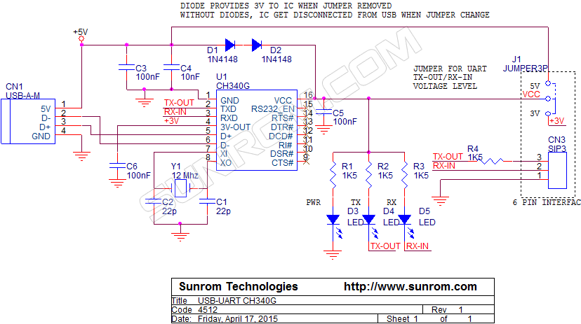
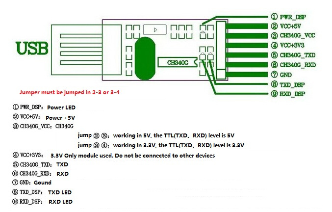
you can find below schematics for the FTDI to program the ESP:
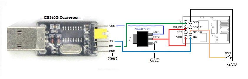
The CH340G converter is really cheap and friendly, in fact, you will find same chip at many different boards with the ESP8266.
GPIO 0 must be connected to GND while programing (SW1 at the image )
Hey @psoro in your schematic of how to hook the esp up to the usb ttl connector, is that top pin supposed to be 5V?
Mine looks like this (flipped over so back is facing up and the usb is pointing to my right):
5V
VCC
3V3
TXD
RXD
GND
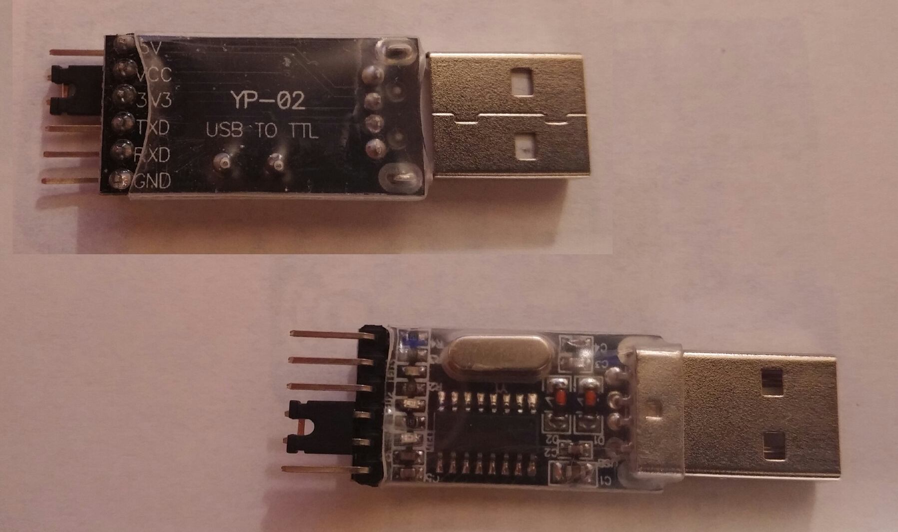
if you move the jumper, you get 3.3 at the third pin right?
Ok. Until here I did step by step. So when I try to complile appear this messagem;
warning: espcomm_sync failed
error: espcomm_open failed
error: espcomm_upload_mem failed
error: espcomm_upload_mem failed
I think its clear thar a I´m having hardware problem, so I[m using a ESP8266 -ESP01 cause a don´t have many space in my project. It is plugged in my arduiino… So what can I do now?
show picture of your hardware.
swap TX & RX
Try reducing the baud rate and if that doesn’t help it might be the way you have set up your hardware i.e. you can’t flash a new sketch if the rx / tx pins are currently tied to something else.