Communication between ESP8266 and Arduino

Board = WeMos ATMega2560 + ESP8266 (LOLIN(WEMOS) D1 R2 & mini in “Boards manager”)

Board on amazon - https://www.amazon.de/dp/B07HML8DZD/ref=pe_27091401_487027711_TE_SCE_dp_2

The task I want this thing to do:
When VirtualPin0 value is HIGH, it sends me PIR sensor readings - they show up in the Blynk IoT app.

So far I have managed to independently control both modules. Got PIR reading from the ATMega2560 in serial monitor and managed to control the ESP8266 from Blynk with virtual pins.

The problem:
I cant understand how to send PIR data from the Mega2560 to ESP8266 to Blynk and the other way around. My guess is that I need to first upload code to the ESP8266 module when mode (5,6,7 - ON, else OFF) is enabled << PICTURE BELOW >> to connect to Blynk servers, then I upload a different code to ATMega2560 using mode (1,2,3,4 - ON, else OFF) and run the whole thing from the same mode. Code is the big problem, because either Im blind or there just isnt enough information about a similar project or the board Im using.

Mode selection on the board:
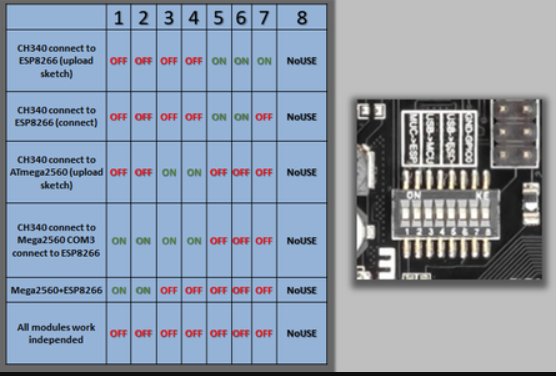
mode_select

Code:

#define BLYNK_TEMPLATE_ID "****"
#define BLYNK_DEVICE_NAME "****"
#define BLYNK_AUTH_TOKEN "********"

#define BLYNK_PRINT Serial


#include <ESP8266WiFi.h>
#include <BlynkSimpleEsp8266.h>

char auth[] = BLYNK_AUTH_TOKEN;
char ssid[] = "****";
char pass[] = "****";

int pirPin = 9;
int sens_value = 0;
int V0value;

BLYNK_WRITE(V0)    // Starts/Stops sending data
{
 V0value = param.asInt();    
 Blynk.virtualWrite(V1, V0value);   // Sends back, if V0 was activated
} 

void setup()
  {
    Serial.begin(115200);
    delay(10);
    Blynk.begin(auth, ssid, pass);
    pinMode(pirPin, INPUT);
  }

void loop()
  {
     if (V0value == HIGH)    
      {
        getPirValue();
      }else{
        Serial.println("OFF");
        delay(1000);  
      }
    Blynk.run();
  }

void getPirValue(void)
  { 
    sens_value = digitalRead(pirPin);
    if (sens_value == HIGH) 
     { 
       Serial.println(1);
       Blynk.virtualWrite(V2, 1);      // Sends back PIR sensor reading
     }if (sens_value == LOW){
       Serial.println(0);
       Blynk.virtualWrite(V2, 0); 
     }
  }

This works fine when uploaded on the EPS8266 module, untill I need to send digitalRead or analogRead value to Blynk, then its just sending 1s, no matter what the sensor is doing. Im guessing its because it cant read theme and the ATMega module has to send the reading to EPS8266? As mentioned before, I dont know how to make theme communicate.
Blynk library v1.0.1
Arduino IdE v1.8.19 (Windows Store 1.8.57.0)
Thanks in advance.

I have to say that you’ve chosen an awful board to use!

I don’t have any personal experience of them (thankfully!) but they are really the worst of both worlds when it comes to using them with Blynk.

The board is primary an AT Mega with an ESP866 connected to hardware serial port COM3 and is the equivalent f these two separate components - a Mega and an ESP-01.
The obvious advantage is that the board overcomes all the messy wiring needed to connect these two boards together.
The problem is that when you’re using a regular Mega + ESP-01 setup with Blynk, the ESP-01 needs to act as a WiFi Modem, and to do this needs to be running the factory “AT” firmware. The sketch is then uploaded to the Mega, not the ESP-01.

The not so obvious disadvantage of your board is that it is very easy to do what you’ve done and put the device into “CH340 connect to ESP8266 (upload sketch)” mode and upload a sketch to the ESP-01. This immediately overwrites the factory AT firmware and prevents the regular Mega + ESP-01 approach from being used.

You can restore the AT firmware, but it’s a tricky process, as you can’t do it via the Arduino IDE.

If you want to run the device in the configuration you’ve adopted then you’ll need two sketches, one running on the ESP-01 to talk to Blynk (and to the Mega) and one on the Mega to control your peripheral devices and talk to the ESP-01.
The advantage of that is the ESP-01 is the more powerful and faster device and because it has native WiFi capabilities you can use some commands that aren’t available when using the Mega + ESP-01 using AT commands for the WiFi connection.

The bottom line is that, unless you need the Mega form-factor to interface with other hardware shields, you’d be far better ditching this board and using either a NodeMCU or ESP32 - depending on how many, and what type of GPIOs you need.

More info on the use of an ESP-01 as a WiFi modem for an Uno/Mega here…

More info on why a NodeMCU type board is preferable, and what its restrictions are here…

Pete.

2 Likes

Thanks for the information, Pete. Will try to get the factory firmware up and running and see how it works out. If I wont figure this out, then I might try the EPS32 + camera module I have lying around, that was supposed to be used in a different project.