My project has been in the making for just over a year now, and once I got it as far as I could (pre-Blynk), I hit a brick wall as I wanted so much for this project to be accessible over the web, the current options available were not what I was looking for, until I found Blynk!
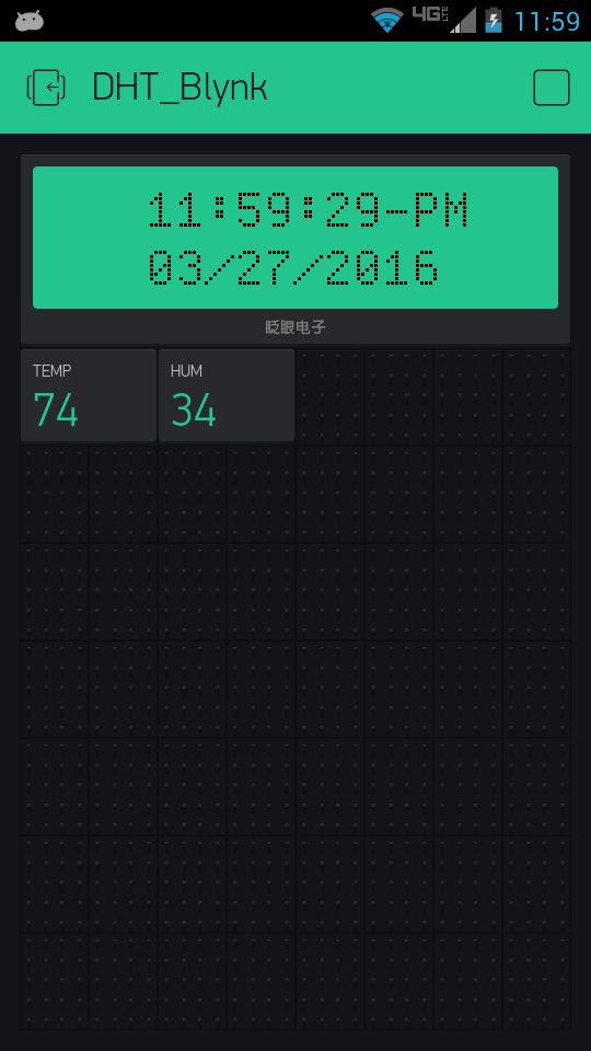
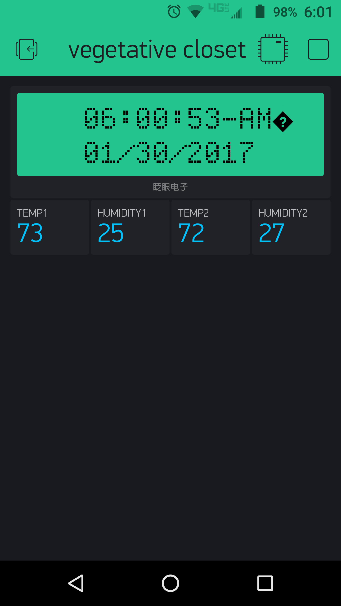
Alas, I now have Blynk and have received ample help from the Blynk community to work out all the bugs that were in my code. I slimmed my sketch down so that it deals only with the data collection and conversions, and now my app has but 3 Widgets to receive all that data.
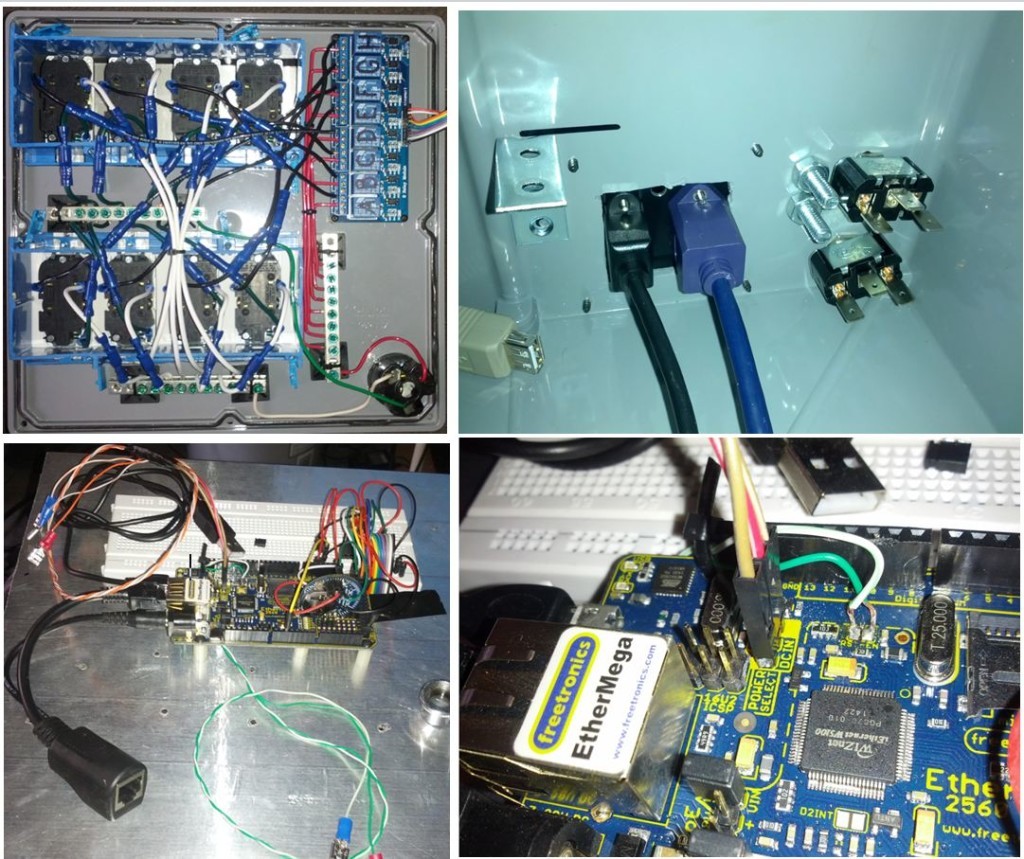
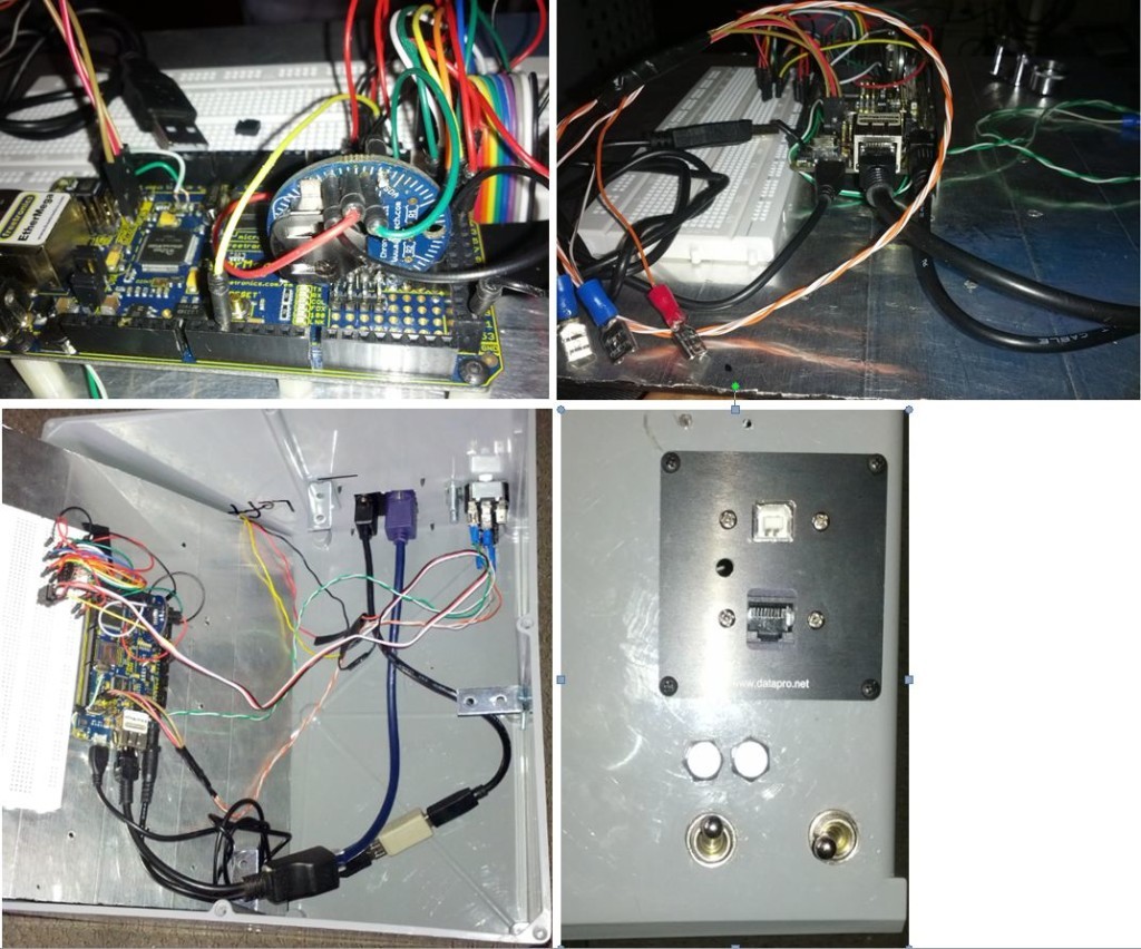
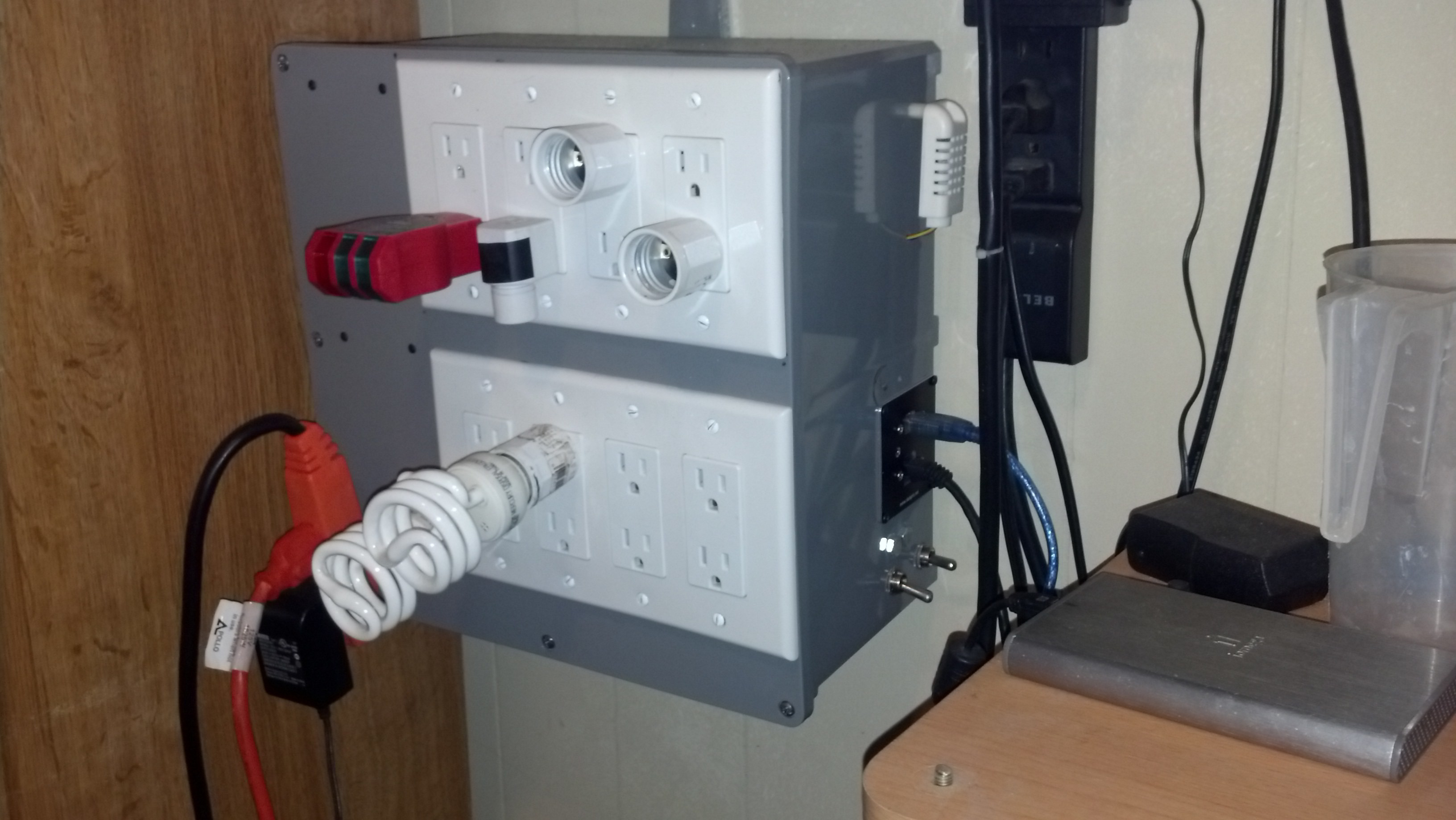
From Home Depot, I purchased a water tight utility box and morphed it into a project box to house my project. On its face is an American style male plug for AC voltage in. I also have 8 duplex AC outlets, each connected to a single channel of my 8 channel Sainsmart relay. As this is a hydroponics controller/greenhouse controller, AC devices can be power cycled in accordance with time kept on the in circuit DS3231 Chronodot RTC, or according to threshold values set against the DHT22 temp/humidity sensor readings.
My MCU is a Freetronics EtherMega (Arduino Mega and Ethernet shield combined). The RTC is an I2C device, and the DHT22 is connected to D13. I also went ahead and cut the RESET-EN trace and soldered some cat5 wire to the pads, and connected the other ends to terminal on a switch so that I can enable or disable this feature of Arduino. When using the serial monitor, the time kept on the RTC would otherwise reset and lose the current time. I also have another switch wired to the EtherMega’s power select header to switch between USB power and DC power. The DC power supply is fed via a Passive POE injector as shown in the pictures. This way, I can locate the project wherever, without needing to be near an AC outlet, plus it looks much cleaner.
I will add the pics, I took some months back, then post the slimmed down version of the code. In another code window, I will also post the other portions of the code that runs the program aside from what Blynk sees. I can later add 8 button widgets to also trigger relays in real time if I ever have need of overriding the programmed times. This is a work in progress and will definitely be getting updated as I accumulate more equipment in need of control, but at this moment, the project can be a stand alone room controller for an indoor garden or greenhouse.
      #include <SPI.h>
      #include <Ethernet.h>
      #include <BlynkSimpleEthernet.h>
      #include <Wire.h>
      #include "DHT.h"                    // DHT data wire connected to D13 with a 10k pullup resistor
      #include <SimpleTimer.h>
      #include "RTClib.h"                 // RealTimeClock Library for DS1307 and DS3231
      #define BLYNK_PRINT Serial
      #include <SPI.h>

//*******Sensor Model********************************
      #define DHTTYPE DHT22
      #define DHTPIN 13

      RTC_DS1307 RTC;
      float UTCOffset = -5.0;    // Your timezone relative to UTC (http://en.wikipedia.org/wiki/UTC_offset)

      char auth[] = "YourAuthKey";

      DHT dht(DHTPIN, DHTTYPE);
      byte h;
      byte f;

      SimpleTimer timer;

      WidgetLCD lcdA(V2);  //Set LCD widget Input to PUSH

    void setup()
    {
      Serial.begin(9600);
      //Serial2.begin() // For other baud rates
      //Serial3.begin() // For other baud rates
      Blynk.begin(auth);
      pinMode(DHTPIN, OUTPUT);
      dht.begin();

      RTC.adjust(DateTime(__DATE__, __TIME__));
      RTC.begin();

      while (Blynk.connect() == false) {}

      timer.setInterval(5000L, climateCheck); // 5 second intervals between DHT readings
      timer.setInterval(3000L, RTCdisplay); // 3 second intervals between RTC readings
    }

    void loop()
    {
      Blynk.run();
      timer.run();
    }

    void climateCheck()
    {
      h = dht.readHumidity();
      f = dht.readTemperature(true);

      Blynk.virtualWrite(V0, f);    //  Set Virtual Pin 0 frequency to PUSH in Blynk app
      Blynk.virtualWrite(V1, h);      //  Set Virtual Pin 1 frequency to PUSH in Blynk app
      //Serial.print(f);
      //Serial.print(h);
    }

    void RTCdisplay()
    {
      DateTime now = RTC.now();  // reads time at beginning of loop

      byte twelveHour = now.hour() - 12; // Variable used to display 13+ hours in 12 hour format
      byte zeroHour = 12;                // Variable use to convert "0" zero hour to display it as 12:00+
      byte displayHour;
      byte MIN = now.minute();
      byte SEC = now.second();
      char* meridian;

      if (now.hour() == 0)  // First we test if the hour reads "0"
    {
      displayHour = zeroHour;
      meridian = "AM";
    }
      else if (now.hour() >= 13)  // if no, Second we test if the hour reads "13 or more"
    {
      displayHour = twelveHour;
      meridian = "PM";
    }
      else
    {
      displayHour = now.hour();
      meridian = "AM";
    }

      char timeStamp[11];
      char dateStamp[11];
      sprintf(timeStamp, "%02d:%02d:%02d-%02s", displayHour, MIN, SEC, meridian);
      sprintf(dateStamp, "%02d/%02d/%04d", now.month(), now.day(), now.year());
      String ts;
      String ds;
      ts = timeStamp;
      ds = dateStamp;

      lcdA.clear();            //Advanced Mode
      lcdA.print(3, 0, ts);    //Advanced Mode
      lcdA.print(3, 1, ds);    //Advanced Mode

    }
and the redacted out code. Use good judgment when adding the following snippets back into the sketch.
#define TURN_ON 0 // TURN_ON and TURN_OFF are defined to account for Active High relays
#define TURN_OFF 1 // Used to switch relay states for on/off of AC devices

#define Relay_A  30  // relay 1 - Mega Pin 30  //  Lights
#define Relay_B  31  // relay 2 - Mega Pin 31  //  Feed Pump(s)
#define Relay_C  32  // relay 3 - Mega Pin 32  //  ------------
#define Relay_D  33  // relay 4 - Mega Pin 33  //  ------------
#define Relay_E  34  // relay 5 - Mega Pin 34  //  Exhaust Fan
#define Relay_F  35  // relay 6 - Mega Pin 35  //  Heater
#define Relay_G  37  // relay 7 - Mega Pin 36  //  Dehumidifier
#define Relay_H  36  // relay 8 - Mega Pin 37  //  ------------

// Sensor Declaration
#define DHTPIN 13     // DHT22 data - pin D13.  A 10k pullup resistor is used to connect data to +5V
#define DHTTYPE DHT22

//  DHT Reference Values - CHANGE THESE TO MANAGE YOUR ROOM'S CLIMATE - //
byte hiMaxTemp = 90;   // temp that triggers heat removal fan on
byte lowMaxTemp = 75;  // temp that triggers heat removal fan off
byte hiMinTemp = 70;   // temp that triggers heater on
byte lowMinTemp = 60;  // temp that triggers heater off
byte hiHum = 75;       // High humidity value that triggers dehumidifier on
byte lowHum = 70;      // Low humidity value that triggers dehumidifier off
//=================================//
//---(Set pins 30-37 as outputs )----
  pinMode(Relay_A, OUTPUT);
  pinMode(Relay_B, OUTPUT);
  pinMode(Relay_C, OUTPUT);
  pinMode(Relay_D, OUTPUT);
  pinMode(Relay_E, OUTPUT);
  pinMode(Relay_F, OUTPUT);
  pinMode(Relay_G, OUTPUT);
  pinMode(Relay_H, OUTPUT);

  digitalWrite(Relay_A, TURN_OFF);  //  This ensures relays do not actuate until called upon
  digitalWrite(Relay_B, TURN_OFF);
  digitalWrite(Relay_C, TURN_OFF);
  digitalWrite(Relay_D, TURN_OFF);
  digitalWrite(Relay_E, TURN_OFF);
  digitalWrite(Relay_F, TURN_OFF);
  digitalWrite(Relay_G, TURN_OFF);
  digitalWrite(Relay_H, TURN_OFF);

  Wire.begin();
//=============================//
  //******************************************************************************************************//
  //***** Alarms for Relays A-D.  Adjust hours and minutes in accordance with 24 hour time format. *******//
  //***** Create tests where true is ON time and false is OFF time. **************************************//
  //***** 18/6 Light Cycle - RELAY_A *********************************************************************//

  boolean relayAstate = false;
  if (now.hour() >= 6) relayAstate = true; //  The test is true from 6-23, and false from 0-5 (18/6)
  if (relayAstate == true)
  {
    digitalWrite(Relay_A, TURN_ON);
    Serial.print("\t");
    Serial.print(F("Vegetative Lights On"));  //  Text printed to serial monitor
    Serial.print("\t");
    Serial.println();
  }
  else
  {
    digitalWrite(Relay_A, TURN_OFF);
    Serial.print("\t");
    Serial.println(F("Vegitative Lights OFf"));  //  Text printed to serial monitor
    Serial.print("\t");
    Serial.println();
  }
  //*********************************** FEED TIMEs - RELAY_B ******************************************//
  // By testing hour once and minute twice, we isolate the "on" time and the duration it is "on". *****//
  // If the Boolean becomes true, D31 is HIGH until Boolean becomes false again. **********************//
  boolean relayBstate = false;
  if (now.hour() == 9 && now.minute() >= 0 && now.minute() < 10) relayBstate = true;    //9:00 am - 10mins
  if (now.hour() == 15 && now.minute() >= 30 && now.minute() < 40) relayBstate = true;  //3:30 pm - 10mins
  if (now.hour() == 22 && now.minute() >= 30 && now.minute() < 33) relayBstate = true;  //10:30pm - 03mins
  if (relayBstate == true)
  {
    digitalWrite(Relay_B, TURN_ON);
    Serial.print("\t");
    Serial.println(F("Feeding Plants"));  //  Text printed to serial monitor
    Serial.print("\t");
    Serial.println();
}
  else
  {
    digitalWrite(Relay_B, TURN_OFF);
  }
  //********************** Unassigned - RELAY_C *******************************//

  //********************** Unassigned - RELAY_D *******************************//

  //******************************** RELAYS E^F^G^H ****************************************//
  //******* Testing the DHT22 sensor temperature in Fahrenheit and humidity in Percent and *//
  //******* actuating Relays based upon those values ***************************************//
  //****************************************************************************************//
delay (1500);

  h = dht.readHumidity();  // assigns humidity reading as "h"
  f = dht.readTemperature(true);  // assigns fahrenheit reading as "f"
  if (isnan(f) || isnan(h))
  {
    Serial.println("Failed to read from DHT");
  }
  else
  {
    float hi = dht.computeHeatIndex(f, h);
    Serial.print(F("Fahrenheit: "));
    Serial.print(f);
    Serial.println("*\t");
    Serial.print(F("Humidity: "));
    Serial.print(h);
    Serial.println("%\t");

  }
  delay(500);

  //   Tests temp & humidity to see if preset values are exceed.
  //   If exceeded, a relay is trigger high to power an exhaust fan or heater.
//**************************** REMOVING HEAT *************************************//
  if (f >= hiMaxTemp)  //if "f" is greater than or equal to hiMaxTemp,
  {
    digitalWrite(Relay_E, TURN_ON);  // TURN_ON relayE (fan).
    Serial.print("\t");
    Serial.println(F("Exhausting the heat!")); //  Text printed to serial monitor
    Serial.print("\t");
    Serial.println();
  }
  else if (f <= lowMaxTemp)  //  or else if "f" is less than or equal to lowMaxTemp
  {
    digitalWrite(Relay_E, TURN_OFF); //  TURN_OFF relay E.
  }
//****************************** ADDING HEAT *******************************//
  if (f <= lowMinTemp)
  {
    digitalWrite(Relay_F, TURN_ON);  // (heater)
    Serial.print("\t");
    Serial.println(F("Warming the room!"));
    Serial.print("\t");
    Serial.println();
  }
  else if(f >= hiMinTemp);
  {
    digitalWrite(Relay_F, TURN_OFF);
  }
//**************************** REMOVING HUMIDITY *******************//
  if (h >= hiHum)
  {
    digitalWrite(Relay_G, TURN_ON);  // (dehumidifier)
    Serial.print("\t");
    Serial.println(F("Drying the air!"));
    Serial.print("\t");
    Serial.println();
  }
  else if (h <= lowHum)
  {
    digitalWrite(Relay_G, TURN_OFF);
  }
}
Initially, my sketch was written to display text to the serial monitor. As I am yet to graft these snippets back in, I myself need to change the code to forward those texts over to Blynk to display as I had always intended to use my cell phone as my projects LCD, I just had no idea how that was going to happen, until I found Blynk.
Thanks to Pavel and team for bringing such a powerful tool to the Maker community!