Hello Blynkers,
After scratching head for few hours and copy paste & editing some codes i finally managed to make it work and it works really great.
Its just blynk controlled relays. But in addition there is an IR receiver to control the relays with any remote (ofc pre programmed the HEX codes into the chip).
And there is a Master Switch (yey!)
Getting the Hex codes
First : get the library for IR Receiver here : https://github.com/markszabo/IRremoteESP8266
Second : connect your IR receiver pins like this
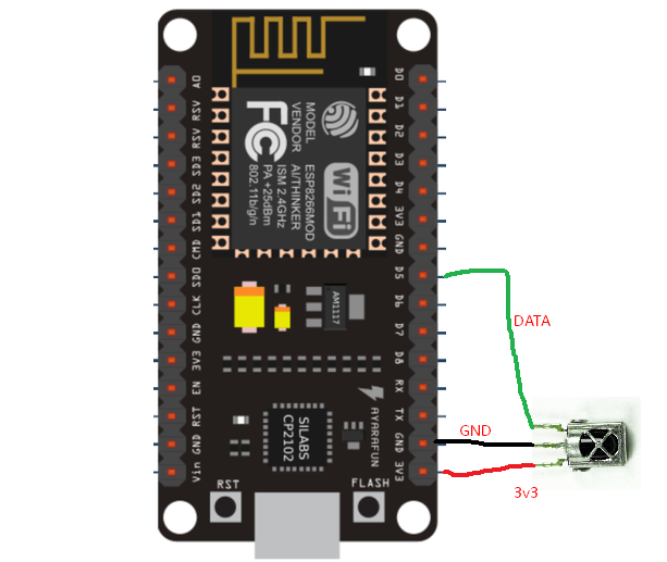
3v3 GND D5 of the MCU to the IR Receiver.
Third : go to example and open IRrecvDemo
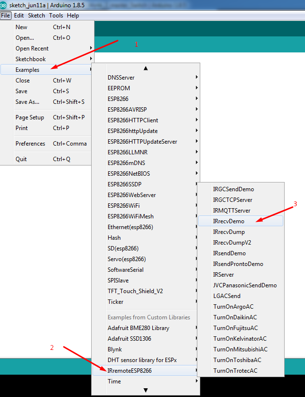
Upload the sketch to your MCU (I used NodeMcu) and open serial monitor, you will see the MCU is waiting to receive the IR signal from your Remote. Point your remote to the Receiver and press any button that you want to use to trigger the relay (or other devices using Digital Pins). Note down the Hex Code of the particular button of your Remote. Repeat the process for other buttons that you are planning to use in the project…
The Code:
#include <ESP8266WiFi.h>
#include <BlynkSimpleEsp8266.h>

// You should get Auth Token in the Blynk App.
// Go to the Project Settings (nut icon).
char auth[] = "auth token";

// Your WiFi credentials.
// Set password to "" for open networks.
char ssid[] = "SSID";
char pass[] = "Password";
//char server[] = "xxx.xxx.xxx.xxx";  // IP for your Local Server
char server[] = "blynk-cloud.com";
int port = 8080;

#ifndef UNIT_TEST
#include <Arduino.h>
#endif
#include <IRremoteESP8266.h>
#include <IRrecv.h>
#include <IRutils.h>

int out1=16; //pin for relay 1 (D0 on nodemcu)
int before1; //state of relay 1
int out2=5;  //pin for relay 2 (D1 on nodemcu)
int before2; //state of relay 2

int beforeall; // state of the master switch

uint16_t RECV_PIN = 14; //Pin for the IR Receiver data pin (14=D5 for Node mcu)
IRrecv irrecv(RECV_PIN);

decode_results results;

void setup(){
   Serial.begin(9600);

  irrecv.enableIRIn(); // start the receiver
  before1=1; //Relay1 is turned off
  pinMode(out1,OUTPUT);
  before2=1; //Relay2 is turned off
  pinMode(out2,OUTPUT);

  beforeall=1; //Master Switch is off at startup

  digitalWrite(out1, HIGH); //Making the pins high to keep the relay board off (for active low relays)
  digitalWrite(out2, HIGH); // make it LOW for active high relay boards.

 Blynk.begin(auth, ssid, pass, server, port);
}

BLYNK_WRITE(V10) //Button Widget is writing to pin V10 that is used for master button in app
{
  int pinData = param.asInt();
  if (pinData==0){    //Code to turn everything ON/OFF : MASTER SWITCH
      digitalWrite(out1,LOW); //turning on the relay1 with master button
      before1=0;
      Blynk.virtualWrite(V1, 0); //telling the app to display the relay1 button on

      digitalWrite(out2,LOW); //turning on the relay2 with master button
      before2=0;
      Blynk.virtualWrite(V2, 0); //telling the app to display the relay2 button on

      beforeall=0; //switched the state of master button status to on
     }
    if (pinData==1){
      digitalWrite(out1,HIGH);    //this is the opposite of the process
      before1=1;
      Blynk.virtualWrite(V1, 1); //to turn off the relays and the button states changed to off

      digitalWrite(out2,HIGH);
      before2=1;
      Blynk.virtualWrite(V2, 1);

      beforeall=1; //master button status changed to off
     }}

BLYNK_WRITE(V1)    // Virtual pin 1 to contlor relay 1
{
  int pinData = param.asInt();
  if (pinData==0){
      digitalWrite(out1,LOW); //relay1 is now turned on
      before1=0;
     }
    if (pinData==1){
      digitalWrite(out1,HIGH); //relay1 is now turned off
      before1=1;
      }}


BLYNK_WRITE(V2) // Virtual pin 2 to contlor relay 2
{
  int pinData = param.asInt();
  if (pinData==0){
      digitalWrite(out2,LOW);
      before2=0;
     }
    if (pinData==1){
      digitalWrite(out2,HIGH);
      before2=1;
      }}


void loop() {
  if (irrecv.decode(&results)) {

//here comes the remote part. the IR decode the hex value and compare

  if (results.value==0x1FE50AF){ //replace the hex code with yours keeping the prefix 0x
    if(before1==1){ // if relay1 state was turned off, then we turn it on
      digitalWrite(out1,LOW);
      before1=0; //relay1 is now turned on
      Blynk.virtualWrite(V1, 0); //sync the data from hardware to app
    }
    else{
      digitalWrite(out1,HIGH);
      before1=1;
      Blynk.virtualWrite(V1, 1);
    }}


  if (results.value==0x1FED827){
    if(before2==1){
      digitalWrite(out2,LOW);
      before2=0;
      Blynk.virtualWrite(V2, 0);
    }
    else{
      digitalWrite(out2,HIGH);
      before2=1;
      Blynk.virtualWrite(V2, 1);
    }}

//the master switch for remote

  if (results.value==0x1FE48B7){ // hex Code to turn everything ON/OFF
    if(beforeall==1){ // if everything were turned off, then we turn them on
      digitalWrite(out1,LOW);
      before1=0;
      Blynk.virtualWrite(V1, 0);

      digitalWrite(out2,LOW);
      before2=0;
      Blynk.virtualWrite(V2, 0);

      beforeall=0;
      Blynk.virtualWrite(V10, 0); //sync the master button to the app
    }
    else{
      digitalWrite(out1,HIGH); // if everything were turned off, then we turn them on
      before1=1;
      Blynk.virtualWrite(V1, 1);
      digitalWrite(out2,HIGH);
      before2=1;
      Blynk.virtualWrite(V2, 1);

      beforeall=1;
      Blynk.virtualWrite(V10, 1);
    }}


irrecv.resume();
  }
 Blynk.run();
}
In the app
V1 for relay 1 and V2 is relay 2. V10 is for Master switch.
I had 8 buttons but to make the code short i removed 6 of em. its easy to copy paste the code and edit few values to add more buttons.
So in short. You have a project that can be used with blynk and with Remote too…
Still the work is in progress to make it better. All the ideas and tips are welcome… 
N.B. - I am a newbie who learned about Blynk months ago and About IR 2 days ago.
Special thanks to GreatScottLab who inspired me to make this project.
Keep Blynk-ing and keep EXPLORING 