Hello,
I am using my wio link with blynk, so to use the grove peripherals with an IoT module. Any idea what the pinout is? I can control the onboard LED, but not stuff that use the grove outlets.
Thanks in advance!
Hello,
I am using my wio link with blynk, so to use the grove peripherals with an IoT module. Any idea what the pinout is? I can control the onboard LED, but not stuff that use the grove outlets.
Thanks in advance!
Hi @eladp,
You can start here:
Regards!
“One thing must be noticed that the power supply of Grove sockets is controlled by a MOSFET switch which is gated by GPIO 15. So you must pull up GPIO 15 in your Arduino sketch to power on the Grove system”
@eladp the power feed to the Grove outlets is controlled by a MOSFET, gated to GPIO 15.
So to use them your sketches will need:
  pinMode(15, OUTPUT);
  digitalWrite(15, 1);
Further details here.
Just checked the Wio with a multimeter and Blynk.
With a button using digital “gp15” in Switch mode it will turn the power on and off to the grove connectors. It is reading 3.36V but note there is a long discharge period (60 seconds) for it to return to close to 0V.
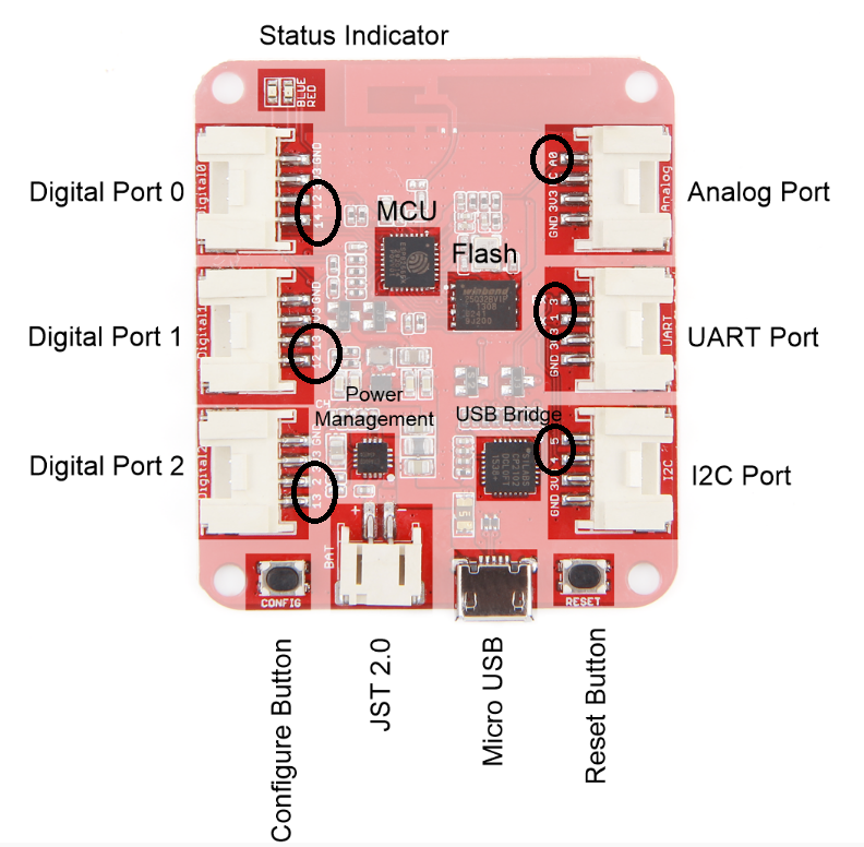
The other thing with Grove is the “duplication” of pins.
So Port 0 has pins 12 and 14, Port 1 has 13 and 12, Port 2 has 2 and 13. Checked Ports 0 and 1 with the meter and confirmed you can access pin 12 from either port etc. That is just the way Grove “works”.
Remember that in Arduino the board selection is Generic ESP8266 but Blynk does have the specific model of “Seeed Wio Link”. Works with Blynk model as ESP8266 for users that want their projects to work with different hardware without changing their projects but remember Wio Link doesn’t have gp0 and gp16 broken out.