Blue Pill - widget on mobile does not display float values

Greetings!
I’m a beginner in Blynk programming and in my first project (garden rover) I encountered a problem displaying float values in a mobile phone widget (in Blynk app v.1.14.2)
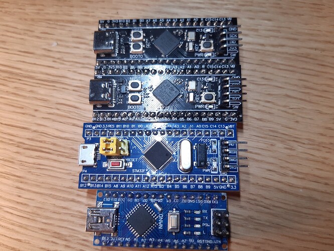
I program in Arduino IDE 2.2.1, controller Blue Pill - STM32F103C8T6 (128 kB), wifi via ESP01 4MB, everything works (DC PWM motors, stepper motors, servos, I/O inputs, etc.), just the display of float/double values is not . It’s about the fact that I need to display the values of Li Ion batteries in volts (“batvolt1” variable) measured by the voltage module, but I can’t do it in the form of a float. I tried the commands as per the manual:

BLYNK_WRITE(V7) {
// float batvolt1 = param.asFloat()
or
// double batvolt1 = param.asDouble();
}

same with Timer:
Blynk.virtualWrite(V7, batvolt1);

If the value is an integer, everything works, if it’s a float or double, it doesn’t. The measured values range from 3.2V to 8.4V.

On the Blynk website, I set the Temlate/Datastreams for the V7 virtual pin to type double, I gave the correct range (0-100), but no effect - on the mobile it shows the last value I measured when I had the V7 as an integer. In addition to the value, the mobile application also displays the Gauge (converted to % battery voltage, i.e. an integer value) without any problems.

Due to the size of the project, I only selected the code for the battery, which I am testing on my own:


/* Fill-in information from Blynk Device Info here */
#define BLYNK_TEMPLATE_ID "xxxx"
#define BLYNK_TEMPLATE_NAME "xxxx"
#define BLYNK_AUTH_TOKEN "xxxx"

#include <ESP8266_Lib.h>
#include <BlynkSimpleShieldEsp8266.h>

// Your WiFi credentials.
// Set password to "" for open networks.
char ssid[] = "SSID";
char pass[] = "password";

#define EspSerial Serial1


#define VSensor PA0               // Voltage sensor pin on BluePill
float vOUT = 0.0;
float vIN = 0.0;
float R1 = 30000.0;
float R2 = 7500.0;
int battery1 = 0;                       // voltge of battery No. 1 for Gauge
float batvolt1 = 0;                   // voltge of battery No. 1 for Value display
unsigned long timer1 = 0;    // an auxiliary quantity for determining a WIFI outage
unsigned long timer2 = 0;    // an auxiliary quantity for determining a WIFI outage
unsigned long error = 0;
bool WiFistatus = LOW;        //WIFI connection status 1= ON, 0= OFF

// This function creates the timer object. It's part of Blynk library
BlynkTimer timer;

/*BLYNK_WRITE(V7) {
float batvolt1 = param.asFloat();                                                     // I have tried this - no effect
}*/

/*BLYNK_READ(V7) {                                                                           // I have tried this - no effect
 Blynk.virtualWrite(V7, batvolt1);
}*/


void myTimer1() {                                           //First timer
                                     
  Blynk.virtualWrite(V12, battery1);        // voltge of battery No. 1 for Gauge
  Blynk.virtualWrite(V7, batvolt1);          // voltge of battery No. 1 for Value display
}

void myTimer2() {                                        // Second timer

  Blynk.virtualWrite(V19, WiFistatus);  // WIFI LED status on Widget
}

void setup() {
    
 // Debug console
  Serial.begin(115200);                               // wifi connection

  pinMode(VSensor, INPUT);                     // AC input of Voltage sensor

  timer.setInterval(1000L, myTimer1);  // Blynk timer
  timer.setInterval(500L, myTimer2);

  if (Blynk.connected()) {                    // synchronization of button values in the application with the server

    Blynk.syncVirtual(V7);
    Blynk.syncVirtual(V12);
    Blynk.syncVirtual(V19);
  }
}

void loop() {

  while (!Blynk.connected()) {                        // When Blynk is not connected
    timer1 = millis();                                           // it starts counting down the duration of the wifi failure
    error = timer1 - timer2;                             //millis difference from the start of the fault

    if (error >= 3000) {                                     // determining the waiting time for a wifi recovery attempt
      Blynk.connect();

      if (Blynk.connected()) {                           //synchronization of button values after recovery
        Blynk.syncVirtual(V7);
        Blynk.syncVirtual(V12);
        Blynk.syncVirtual(V19);
      }
    }
  }

  WiFistatus = HIGH;                        // Widget LED of wifi status on - if no signal, after 1 sec. V19 set to OFF

  // Analog Voltage sensor calculation:
  int value = analogRead(VSensor);
  vOUT = (value * 3.3) / 1024.0;
  vIN = vOUT / (R2 / (R1 + R2));
  int transfer1 = vIN * 1000;                                      // if I don have float value on display, must have miliVolts
  batvolt1 = vIN;                                                           // this is problematic float value

  battery1 = map(transfer1, 6000, 8400, 0, 100);  // Gauge(%) of 6000 - 8400 mV for Li Ion Battery

  // runs BlynkTimer
  timer.run();
}

Thank you for your help. Radoslav
Okay, let’s start with some basic information that you omitted from your initial post…

• Blynk server region
• Blynk Library version

BLYNK_WRITE(vPin) is a command that is triggered automatically when the value of the vPin datastream changes on the Blynk server. This is normally used to obtain the value of a switch or slider widget from the Blynk dashboard. It has no use in this sketch.

You’ve also tried using BLYNK_READ(vPin) in your sketch, which is not supported in Blynk IoT.

You need to stop doing this…

And you need to move this code out of your void loop into a timed function…

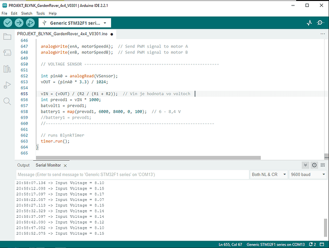
I’d suggest that you add some serial print commands to display the value of batvolt1 in your serial monitor, to verify that the calculated value is in fact a float.

Pete.

Thank you for fast reply.

To begin with, I will fill in the missing data:

• Blynk server region:
Region: fra1
• Blynk Library version:
version=1.3.2

First, I moved the Blynk server connection testing to Timer1 in the code as recommended.
Then I added in the beginning part of the program:

HardwareSerial Serial2(PA3, PA2);

and created Timer 3 where I placed the command:

void myTimer3() { // Timer No. 3.
   // Print results to Serial Monitor
   Serial2.print("Input Voltage = ");
   Serial2.println(vIN);
}

in setup added

timer.setInterval(5000L, myTimer3);

After connecting the Serial Monitor, the decimal values of the voltage started to be displayed.
As I defined in the beginning of the program

float batvolt1 = 0.00; // voltage of battery No. 1

Serial Monitor was showing decimal values correctly. However, it didn’t show any new value in the mobile application, and not a decimal number at all.
After defining:

double batvolt1 = 0.00; // voltage of battery No. 1

there was no value displayed on the Serial Monitor and also no new values (even decimal) were displayed in the mobile application (Presumably Blue Pill doesn’t know double?)

​Radoslav.

I don’t really understand what you are saying here.
You seem to be saying that no values are being updated in the app, either integers or floats. Is this correct?

I’d suggest that you post your updated sketch.

When you post serial monitor output it needs to be text, not a screenshot, and it needs to be formatted with triple backticks.
I’d suggest you post your serial output from boot-up, so we can see the Blynk logo and connection data, as well as some values.

You need to be clear about exactly what is being displayed in the dashboard, and whether this is the mobile or web dashboard (or both).

Your issue does sound similar to this one…

but that was fixed (at least for the nano) in the latest release.

Pete.

Greetings.
I tried to improve the program and test it on two different types of microcontrollers - Arduino NANO and STM32 - BluePILL (STM32F103C8T6 128kB), BlackPILL (STM32F411CEU6 512kB) and
BlackPILL (STM32F401CCU6 256kB), probably all clones.

The program for NANO is almost identical to the program for STM32, I just added the Software Serial library (used for Serial Monitor), because NANO has only one Hardware Serial (used for WIFI - ESP0). In addition, the voltage calculation formula for the VOLTAGE sensor is slightly different in the program for STM32, where 3.3 V is defined in the voltage calculation formula and 5 V for the NANO - due to the different voltage of the TTL logic.

Two virtual pins are used in the program to display the voltage values, one to transfer the integer value of the battery voltage (variable int battery1, pin V12), this one is used to display the values in the Widget “GAUGE” of battery % on the web dashboard and on the mobile dashboard. The second virtual pin is used to display the float value of the measured voltage (float variable batvolt1, pin V7) in the widget “LABEL” on the web dashboard of BLYNK and “VALUE DISPLAY” on mobile. To check functionality, measured values from the microcontroller are also displayed via UART on the Serial Monitor ARDUINO IDE in my PC.

The test result was as follows:

  1. Arduino NANO:
  • mobile: a) GAUGE (integer value): all OK
    b) VALUE DISPLAY (float value): all OK
  • WEB Blynk: a) GAUGE (integer value): all OK
    b) LABEL (float value): all OK
  • PC Serial Monitor: float values - all OK
  1. STM 32 (STM32F103C8T6, STM32F411CEU6, STM32F401CCU6):
  • mobile: a) GAUGE (integer value): all OK
    b) VALUE DISPLAY (float value): NOTHING
  • WEB Blynk: a) GAUGE (integer value): all OK
    b) LABEL (float value): NOTHING
  • PC Serial Monitor: float values - all OK

The result could be interpreted so that Blynk currently does not support the transfer of float values via virtual pins in BluePILL and BlackPILL microcontrollers (STM32F103C8T6, STM32F411CEU6, STM32F401CCU6)…

Sketch for NANO:

// SKETCH FOR ARDUINO NANO

/* Fill-in information from Blynk Device Info here */
#define BLYNK_TEMPLATE_ID "XXX"
#define BLYNK_TEMPLATE_NAME "XXX"
#define BLYNK_AUTH_TOKEN "XXX"


#include <ESP8266_Lib.h>
#include <BlynkSimpleShieldEsp8266.h>
#include <SoftwareSerial.h>

SoftwareSerial swSerial(2, 3);  // RX, TX - for Serial Monitor

// Your WiFi credentials.
// Set password to "" for open networks.
char ssid[] = "XXX";
char pass[] = "XXX";

// Hardware Serial on Mega, Leonardo, Micro...
#define EspSerial Serial
//HardwareSerial Serial2(PA3, PA2);

// Your ESP8266 baud rate:
#define ESP8266_BAUD 115200

ESP8266 wifi(&EspSerial);

//-----------------------------------------------------------------
#define VSensor A6        // Voltage sensor pin on NANO
#define iLED LED_BUILTIN  //BUILD IN LED
float vOUT = 0.0;
float vIN = 0.0;
float R1 = 30000.0;
float R2 = 7500.0;
int battery1 = 0;          // voltge of battery No. 1 for Gauge
float batvolt1 = 0.0;      // voltge of battery No. 1 for Value display
unsigned long timer1 = 0;  // an auxiliary quantity for determining a WIFI outage
unsigned long timer2 = 0;  // an auxiliary quantity for determining a WIFI outage
unsigned long error = 0;
bool WiFistatus = LOW;  //WIFI connection status 1= ON, 0= OFF

// This function creates the timer object. It's part of Blynk library
BlynkTimer timer;


void myTimer1() {                     //First timer
                                      // This function describes what will happen with each timer tick
                                      // e.g. writing sensor value to datastream V5
  Blynk.virtualWrite(V12, battery1);  // voltge of battery No. 1 for Gauge
  Blynk.virtualWrite(V7, batvolt1);   // voltge of battery No. 1 for Value display
  // Print results to Serial Monitor
  // Serial2.print("Input Voltage = ");
  //Serial2.println(vIN);
  swSerial.print("Input Voltage = ");
  swSerial.println(vIN);


  while (!Blynk.connected()) {  // When Blynk is not connected
    timer1 = millis();          // it starts counting down the duration of the wifi failure
    error = timer1 - timer2;    //millis difference from the start of the fault

    digitalWrite(iLED, LOW);
    HOLD2(300);
    digitalWrite(iLED, HIGH);
    HOLD2(300);
    digitalWrite(iLED, LOW);

    if (error >= 3000) {  // determining the waiting time for a wifi recovery attempt

      Blynk.connect();


      if (Blynk.connected()) {  //synchronization of button values
        Blynk.syncVirtual(V7);
        Blynk.syncVirtual(V12);
        Blynk.syncVirtual(V19);
      }
    }
  }
}

void myTimer2() {  // Second timer

  Blynk.virtualWrite(V19, WiFistatus);  // WIFI LED status on Widget
}

//DELAY funktion ****************************************************************
void HOLD2(int STOP) {
  unsigned long STOPmls = millis() + STOP;
  while (millis() < STOPmls) {
    //Blynk.run();
  }
}

//****************************************************************
void setup() {

  // Debug console
  Serial.begin(115200);  // wifi connection
  swSerial.begin(9600);

  pinMode(VSensor, INPUT);  // Analog input of Voltage sensor
  pinMode(iLED, OUTPUT);    // BUILD IN LED 

  // Set ESP8266 baud rate
  EspSerial.begin(ESP8266_BAUD);
  delay(10);
  Blynk.begin(BLYNK_AUTH_TOKEN, wifi, ssid, pass);


  timer.setInterval(1000L, myTimer1);  //Blynk timer
  timer.setInterval(500L, myTimer2);

  if (Blynk.connected()) {  // synchronization of button values in the application with the server

    Blynk.syncVirtual(V7);
    Blynk.syncVirtual(V12);
    Blynk.syncVirtual(V19);
  }
}

void loop() {

  digitalWrite(iLED, HIGH);  // BUILD IN LED ON
  WiFistatus = HIGH;         // Widget LED of wifi status on - if no signal, after 1 sec. V19 set to OFF

  // Analog Voltage sensor
  int value = analogRead(VSensor);
  vOUT = (value * 5) / 1024.0;
  vIN = vOUT / (R2 / (R1 + R2));
  int transfer1 = vIN * 1000;  // if I don have float value on display, must have miliVolts
  batvolt1 = vIN;              //float value of voltage


  battery1 = map(transfer1, 6000, 8400, 0, 100);  // Gauge(%) of 6000 - 8400 mV for Li Ion Battery


  // runs BlynkTimer
  timer.run();
}


Sketch for STM32:

//SKETCH FOR BluePILL / BlackPILL

/* Fill-in information from Blynk Device Info here */
#define BLYNK_TEMPLATE_ID "XXXX"
#define BLYNK_TEMPLATE_NAME "XXXr"
#define BLYNK_AUTH_TOKEN "XXX"


#include <ESP8266_Lib.h>
#include <BlynkSimpleShieldEsp8266.h>

// Your WiFi credentials.
// Set password to "" for open networks.
char ssid[] = "XXX";
char pass[] = "XXX";

// Hardware Serial on Mega, Leonardo, Micro...
#define EspSerial Serial1
HardwareSerial Serial2(PA3, PA2);  // RX, TX - for Serial Monitor

// Your ESP8266 baud rate:
#define ESP8266_BAUD 115200

ESP8266 wifi(&EspSerial);

//-----------------------------------------------------------------
#define VSensor PA0  // Voltage sensor pin on BluePill
#define iLED PC13    //BUIL IN LED
float vOUT = 0.0;
float vIN = 0.0;
float R1 = 30000.0;
float R2 = 7500.0;
int battery1 = 0;          // voltge of battery No. 1 for Gauge
float batvolt1 = 0.0;      // voltge of battery No. 1 for Value display
unsigned long timer1 = 0;  // an auxiliary quantity for determining a WIFI outage
unsigned long timer2 = 0;  // an auxiliary quantity for determining a WIFI outage
unsigned long error = 0;
bool WiFistatus = LOW;  //WIFI connection status 1= ON, 0= OFF

// This function creates the timer object. It's part of Blynk library
BlynkTimer timer;

void myTimer1() {                     //First timer
                                      // This function describes what will happen with each timer tick
                                      // e.g. writing sensor value to datastream V5
  Blynk.virtualWrite(V12, battery1);  // voltge of battery No. 1 for Gauge
  Blynk.virtualWrite(V7, batvolt1);   // voltge of battery No. 1 for Value display
  // Print results to Serial Monitor
  Serial2.print("Input Voltage = ");
  Serial2.println(vIN);

  while (!Blynk.connected()) {  // When Blynk is not connected
    timer1 = millis();          // it starts counting down the duration of the wifi failure
    error = timer1 - timer2;    //millis difference from the start of the fault

    digitalWrite(iLED, LOW);
    HOLD2(300);
    digitalWrite(iLED, HIGH);
    HOLD2(300);
    digitalWrite(iLED, LOW);

    if (error >= 3000) {  // determining the waiting time for a wifi recovery attempt

      Blynk.connect();


      if (Blynk.connected()) {  //synchronization of button values
        Blynk.syncVirtual(V7);
        Blynk.syncVirtual(V12);
        Blynk.syncVirtual(V19);
      }
    }
  }
}

void myTimer2() {  // Second timer

  Blynk.virtualWrite(V19, WiFistatus);  // WIFI LED status on Widget
}

//DELAY funktion***********************************************************
void HOLD2(int STOP) {
  unsigned long STOPmls = millis() + STOP;
  while (millis() < STOPmls) {
    //Blynk.run();
  }
}

//****************************************************************
void setup() {

  // Debug console
  Serial.begin(115200);  // wifi connection
  Serial2.begin(9600);

  pinMode(VSensor, INPUT);   // Analog input of Voltage sensor
  pinMode(iLED, OUTPUT);     // BUILD IN LED
  digitalWrite(iLED, HIGH);  // BUIL IN LED OFF  -it's the reverse logic

  // Set ESP8266 baud rate
  EspSerial.begin(ESP8266_BAUD);
  delay(10);
  Blynk.begin(BLYNK_AUTH_TOKEN, wifi, ssid, pass);


  timer.setInterval(1000L, myTimer1);  //Blynk timer
  timer.setInterval(500L, myTimer2);

  if (Blynk.connected()) {  // synchronization of button values in the application with the server

    Blynk.syncVirtual(V7);
    Blynk.syncVirtual(V12);
    Blynk.syncVirtual(V19);
  }
}

void loop() {

  digitalWrite(iLED, LOW);  // BUIL IN LED ON -it's the reverse logic
  WiFistatus = HIGH;        // Widget LED of wifi status on - if no signal, after 1 sec. V19 set to OFF

  // Analog Voltage sensor
  int value = analogRead(VSensor);
  vOUT = (value * 3.3) / 1024.0;
  vIN = vOUT / (R2 / (R1 + R2));
  int transfer1 = vIN * 1000;  // if I don have float value on display, must have miliVolts
  batvolt1 = vIN;              //float value of voltage

  battery1 = map(transfer1, 6000, 8400, 0, 100);  // Gauge(%) of 6000 - 8400 mV for Li Ion Battery


  // runs BlynkTimer
  timer.run();
}


Radoslav.

@vshymanskyy it looks like the issue you previously fixed with float values not working on the Nano (see link in one of the posts above as a reminder) also exists with the blue and black pill devices being discussed above.

Is this something you could take a look at please?

Pete.