@kalazino 2700 Energy units.
great, really a great project.
It would be possible to implement the function to remember the last state of the pin and then re-enable the device when it was on before the restart?
thank you so much
This is already available. Check the docs for “sync state”
Hi, this is just awesome., there is a small issue
i have set the time zone to india and it works for all modes but for ALL Days
it changes to Europe Madrid.
I want to put it for my Aquarium , schedule lights for all day
Also, can all of my 4 relays be scheduled in this manner. ??
Also, i noticed when the hardware goes offline. it does not get the current status of buttons pressed.
By default the QR code for the 4 timers have TZ selection disabled. Try setting them all to YES.
It would be difficult with an ESP-01.
@psoro I have been doing some work with the ESP01’s recently even though I’m not a massive fan compared with the plug and play ESP boards. Could you please knock up a basic circuit diagram for your scheduler. I can see a cap to the right of the HLK-PM01 but I just wondered what other components you have lurking away on the board.
Hi @Costas, this is something I should have done time ago…
Here you are:
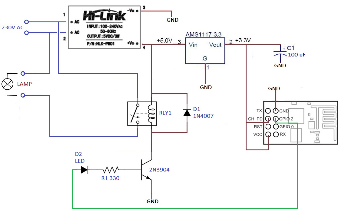
I want to add a IR Receiver sensor at GPIO 0… hopefully in a few weeks I’ll post an update with new functions.
Regards!
2 Likes
Dear @psoro,
out of curiocity, why you put D2 LED diode? What it does?
Thanks and Best Regards,
Mike Kranidis
@mikekgr I think it’s simply an LED to indicate GPIO 2 is HIGH (or LOW) as shown on the photo in the OP (half hidden under the ESP01).
Dear Costas,
yes I saw the picture above. It is very strange to light up a LED diode, that needs at least 10mA to light up good, using GPIO pin as “command”, then 330Ω resistor in series and finally the base of a NPN transistor all in series.
I can guess that only at minimum this LED can be lighting or I lost my engineering knowledge …
Hi @mikekgr, @Costas,
You have pointed at the main concern here… If I’m not wrong (cause I did this board time ago…) at the beginning I had issues to use the ESP-01 attached to the base of the NPN transistor. After turning on the board, the ESP-01 went directly (depending on the GPIO) into Flash mode or with the blue light “on” without having its control…(the ESP-01 does some “dance” with the GPIO’s at startup) so I decided to do some trials cause a simple “Relay board” worked fine but not my board… In the middle of the trial and error I added the LED (cause I wanted to see what was happening at the GPIO) with the 330Ω resistor and it worked… I did a second board and the result was OK also so the issue was closed  , at that time, I was too tired to check the current base or other stuff of the NPN transistor… I was happy to be able to solve it… that’s all I needed to go to sleep peacefully…
Dear @psoro,
Thanks for your answer. It is worth some day to measure the transistor base current with GPIO at both states. If you do that, please let me know.
Best Regards,
Mike Kranidis
@mikekgr, unfortuntelly I haven’t got more 2N3904 transistors to play with… I’ll try to remember this conversation next time at the electronic shop…
Kind regards!!!
1 Like
Guys,
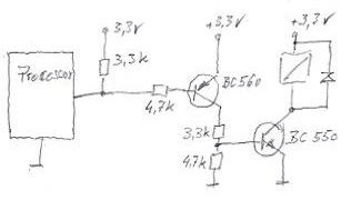
since I received a lot of help from this forum I wanted to share my solution to correctly connecting a relais to the ESP-01. Its important to have the pullup when you connect to GPIO0/2. Also, I have chosen the two transistor setup to not invert the signal (or double invert it in a sense).
I hope this helps someone as I have seen a lot of sub-optimal solutions in the web. The solution shown here with a 330 Ohm and a diode is definitely not a correct and valid solution and is endangering the ESP as it draws too much current.
Hi @mroggi,
Thanks for your suggestions, I’ll give a try but I’m not sure about your statement:
Please, have a look at the below pictures,@mikekgr, please see also:
As per my sketch (for sure not the best one…), the current at the base would be 1.51mA
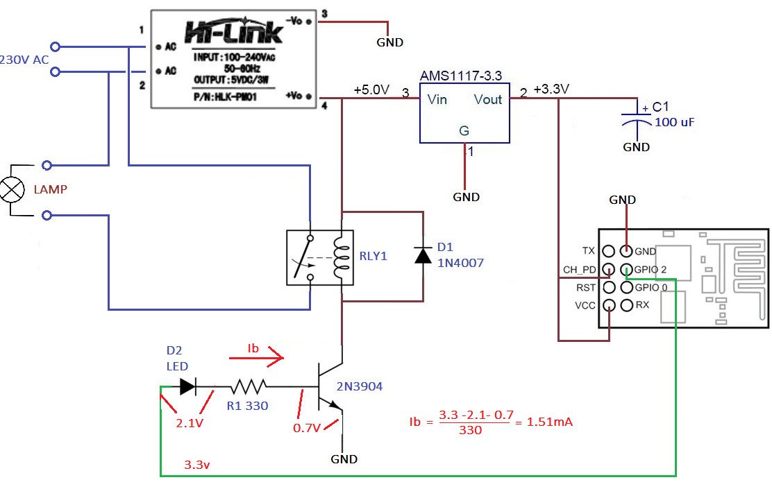
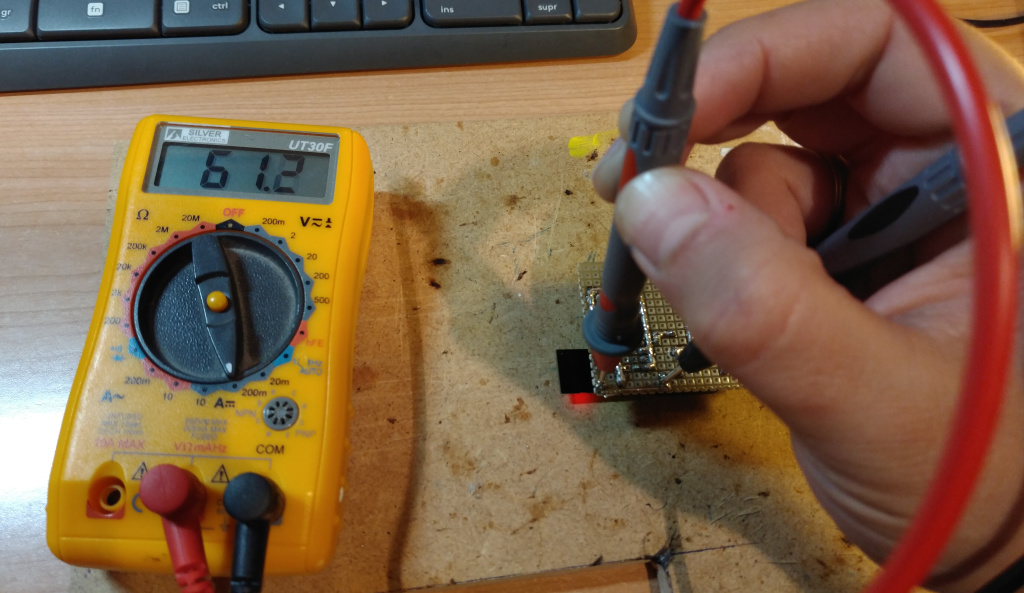
The measure shows 1.48mA.

The current at the collector is 61.2mA:
I guess ESP can manage 1.48mA without issues… ![]()
Kind regards!
1 Like
Dear @psoro nice work… !
Well 1.51mA for the transistor base is just fine. Does this current light up the LED? ( As I see in the picture, yes, but is it bright enough or dimmed ? ).
Best Regards,
Mike Kranidis
one suggestion, it is better, in order to calculate the ib to measure the voltage across R1 and exactly the value of R1… ib = VR1 / R1 …
Thanks @mikekgr, I can ensure you that the fact to measure and take the picture at the same time has not been really easy… two hands are not enough!
Quite dimmed
Agree but the Resistor is underneath the ESP and not easy to do the measurement.
Regards!
1 Like
Thank you for sharing your project, how could I increase ignition and shutdown events every day? Thanks for help
Hi @gionni, at the moment this is not possible using my project BUT for your request the Eventor widget could be your best friend! Give it a try