While this forum is NOT about Mains wiring… and ALL MAINS wiring recommendations and diagrams “should” be treated as for “PROFESSIONAL USE ONLY!”… some may “forget” to read the fine print, or may not understand it, and after glancing at the pretty picture, say, oh, I’ll try that.
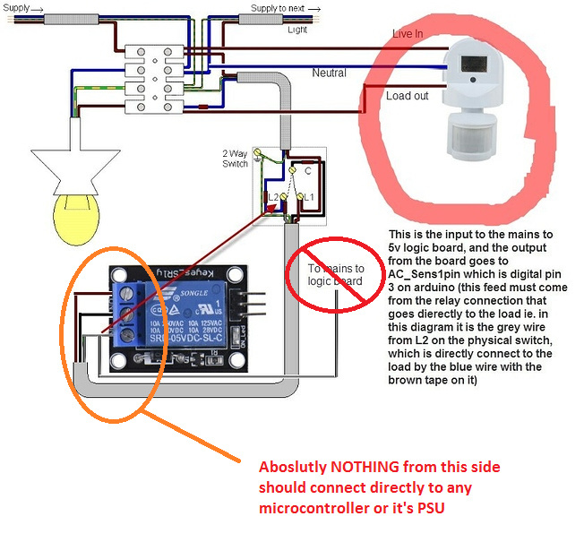
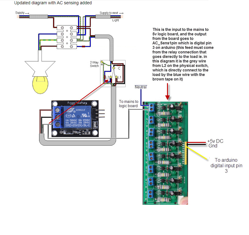
You should make sure any diagrams are VERY clear that there is to be a mains isolated sensor in-between your gray wire and any MCU.
I thought that was pretty clear in the text with the diagram - the grey wire does go to the mains logic board which is an optoisolated 240v mains to ttl logic signals. So the grey wire does indeed go to the input side(mains) of the mains to logic board.
I’m not sure what you want to do here it’s getting a little lost in translation. If you are not using mains then I have a totally different setup that uses 5v ttl signals from the light switch to operate a two circuit
Yes… but I was responding to @leomaralmonte, whom seemed unsure… marking the motion sensor and indicating that it was the isolated testing board??
I honestly thought he had added in the grey wire and words instead of diagram for the isolated sensor… I was comparing to your initial diagram (I missed seeing the modified one mid-way). My bad on that one.
That said, I would have still put in an image of the “mains to 5v logic board” instead of lots of words… but then I am a visual learner
I am really worried that you do not understand enough about mains wiring here to attempt this project. the green and yellow striped wire is the earth for the circuit. It does not connect anywhere on the relay.
Do you know what the circuit is actually designed for and what it is doing with the blynk app ???
240VAC and 12VDC circuits can be drastically different. This is a Blynk forum, not a self-administered shock therapy advice line No more electrical questions please… go talk to a professional electrician for that, else your Capstone might become your Headstone.
Thnak you! Yes this is the exact projet we are working on. We are monitoring the lights if it is on or off. This projet of yours was the answer. It gives feedback to the Blynk app if the state of the lights is on/off.
My point is that diagram, as all others when bounced around in forums like this, is just an example… NOT to be taken as always correct.
If this is exactly what you are doing then honestly you shouldn’t be doing it, as you have already stated you are unfamiliar with the concepts. And an even a clear diagram like provided by @newdos may be totally wrong and even dangerous for your needs if you blindly (aka without knowledge) try to duplicate it in real life. We can’t stop you, but use at your own risk and ask for clarification with a local professional, not here.