I have v1.13.1(145) of the android app installed but only one of my 3 devices that were created in Blynk.cloud are showing up. Same goes for the templates (1 device per temlate). My understanding is that if a device or template is created on my PC (cloud UI) then my devices and templates should both show up in the android app automatically, but this is not happening. I have verified both my phone and my devices are on the same wifi network, but even if I try “Find devices nearby”, I get no results.
Another issue is that for the one device I do have set up on the android app, it shows offline on the app AND the web dashboard.
Not overly impressed especially since I just upgraded from the free to the next tier 10 device subscription.
Any help would be appreciated.
Thanks
That is correct.
Have you tried logging-out of the app on your Android device and logging-back in?
Not necessary
You wouldn’t expect to find any devices unless you had a board that you’d flashed with Edgent code as was in un-provisioned state.
What does your serial monitor for that device show?
How did you do this upgrade? Did you convert an existing free account into a Plus or Pro account, or did you sign-up to a new account?
Did you do this “upgrade” via the web console or via the app?
Pete.
Pete, first of all, thanks for your help.
Yes, I did log out and log back in. I even restarted the phone just in case. No luck
I’m not sure I understand what either edgent code or un-provisioned state mean. I flashed the ESP8266 via my PC USB from Arduino cloud connection. This is the same thing I did for the one device that did show up. Does it matter if the ESP8266 had a different sketch loaded before? Id so, how do I clear that so it will show up in the app like it’s supposed to?
Putty shows it is connected. Also, I included code to flash an LED on the ESP8266 and on the dashboard only when it is connected to wifi, and they are flashing indicating to me that they are active.
I upgraded my existing account from free to Plus (or whatever the 10 device one is) from the web/cloud console directly. I did not create a separate account, but good question.
Thanks again for your help!
Much of what you’ve said makes no sense in Blynk terms.
I’d suggest that you start by posting your sketch (correctly formatted with triple backticks), your serial monitor output (as text, also with triple backticks) and screenshots from your app and web console showing the templates and devices you have visible in both.
Pete.
Exactly what of my reply made no sense? About how I logged out and back in with no positive result? The part where I paid for an upgrade? The part where this is supposed to just work without all the hassle?
And how exactly am I supposed to perform this “(correctly formatted with triple backticks)” anyway? I am not a professional blogger and have no idea what you are talking about.
Is there no way to talk to someone from Blynk support to explain why none of this is working properly even though, as far as I know, I have created all 3 devices in the same way on the web cloud UI?
Insulting me is not a good way to help and I don’t appreciate it.
To flash the device via a cloud connection, rather than a USB connection, you need your device to be running some sort of Over The Air (OTA) code running on your device.
But, unless you’re running something like a Particle device, you need to do the initial flashing via a wired (USB) connection.
So, this statements makes no sense from a Blynk point of view.
If you’re using PuTTY as your serial monitor rather than the Arduino IDE then it would be worth explaining why, but also sharing your PuTTY/Serial monitor output.
When you created this topic it was pre-populated with information about the type of information to provide, and how to post code (with triple backticks).
If you don’t know what triple backticks are, or how to use them, then a quick search of this forum would have given you all the information you need.
Blynk staff do read this forum, and if you have a Plus plan then that is the way to contact them. However, they’ll ask you the same questions as I did, and until you provide that level of information you’ll find it difficult to get answers to your questions.
Pete.
OK, let’s try again. You said “you need to do the initial flashing via a wired (USB) connection”, which is exactly what I said I did. I did not do an OTA flash, I was logged into my Arduino Cloud account on my PC. Not sure what part of this makes no sense as it is the only way I have ever flashed an ESP8266. The same as I did for the 1 device that is showing up on the App.
I’ve used puTTY because that’s what I learned to use from various online instructions. Not even sure how to use the Arduino Cloud UI as a serial monitor. I don’t have the ESP8266 in hand to provide that output and not sure that it matters. The LED’s are flahsing indicating the wifi connection is good. Still not sure why the Blynk Web and Android App dashboards say it is offline when it is not.
Here is the code for the sketch I am currently trying load on the app:
#define PULSE_PIN D2  //gpio4
#define FLOW_CALIBRATION 5.5  //new value for Gredia GR-105 F=(5.5*Q)±2% Q=L/Min
#define VPIN_TOTAL_GALLONS      V1
#define VPIN_FLOW_RATE          V2
#define VPIN_FLOW_MILLI_LITERS  V3
#define VPIN_RESET              V4
#define OTA_HOSTNAME "Test Flow Sensor Water Meter"

#include <ESP8266WiFi.h>
#include <BlynkSimpleEsp8266.h>

char auth[] = BLYNK_AUTH_TOKEN;

BlynkTimer timer;

volatile long pulseCount = 0;
float flowRate;
unsigned int flowMilliLitres;
unsigned long totalMilliLitres;
float totalLitres;
float totalLitresold;
unsigned long oldTime;
float flowRateGallons; //active flow rate provide conversion rate from Liters to Gallons - divide flowrate by 3.785
unsigned long totalGallons; //cumulative Gallons
float totalgallonssold; //pulls value of V1 from Blynk
float histgallons; //cumulative Gallons from Blink on V1 plus new volume
float literToGallons = 3.78541;


BLYNK_CONNECTED() { // runs once at device startup, once connected to server.
 Blynk.syncVirtual(VPIN_TOTAL_GALLONS); //gets last know value of V1 virtual pin from blynk server
}


// Restores last know value of V1 virtual pin which we got from blynk server
BLYNK_WRITE(VPIN_TOTAL_GALLONS)
{
 totalgallonssold = param.asFloat();
}


BLYNK_WRITE(VPIN_RESET) {  // reset all data with button in PUSH mode on virtual pin V4
 int resetdata = param.asInt();
 if (resetdata == 0) {
   Serial.println("Clearing Data");
   Blynk.virtualWrite(VPIN_TOTAL_GALLONS, 0);
   Blynk.virtualWrite(VPIN_FLOW_RATE, 0);
   flowRate = 0;
   flowMilliLitres = 0;
   totalMilliLitres = 0;
   totalLitres = 0;
   totalLitresold = 0;
   flowRateGallons  = 0; //LK added this block to provide conversion rate from Liters to Gallons
   totalGallons    = 0;
   totalgallonssold = 0;
   histgallons = 0;
 }
}

void pulseCounter()
{
 pulseCount++;
}

void flow()
{

 if ((millis() - oldTime) > 1000)   // Only process counters once per second
 {
   detachInterrupt(PULSE_PIN);
   flowRate = ((1000.0 / (millis() - oldTime)) * pulseCount) / FLOW_CALIBRATION;  //flowrate in liters per minutes
   flowRateGallons = (flowRate / literToGallons); //LK added to directly convert liters to gallons
   oldTime = millis();
   flowMilliLitres = (flowRate / 60) * 1000;
   totalGallons += flowRateGallons; //LK added next 2 lines for liter to gallon conversion
   totalMilliLitres += flowMilliLitres;

   unsigned int frac;

   // Print the flow rate for this second in Gallons / minute to Putty serial monitor
   Serial.print("flowRateGallons: "); //active flow rate
   Serial.print(int(flowRateGallons));  // Print the integer part of the variable
   Serial.print(".");             // Print the decimal point
   frac = (flowRateGallons - int(flowRateGallons)) * 10; // Determine the fractional part. The 10 multiplier gives us 1 decimal place.
   Serial.print(frac, DEC) ;      // Print the fractional part of the variable
   Serial.print("G/min");

   Serial.print("  Output Liquid Quantity: ");  // Print the cumulative total of Gallons flowed since starting
   Serial.print(totalGallons);  //replaced histgallons with totalGallons as they showed the same results - don't need histgallons
   Serial.println("G");

   pulseCount = 0;  // Reset the pulse counter so we can start incrementing again

   attachInterrupt(PULSE_PIN, pulseCounter, FALLING);    // Enable the interrupt again now that we've finished sending output
 }
}

void sendtoBlynk()  // In this function we are sending values to blynk server
{
 Blynk.virtualWrite(VPIN_TOTAL_GALLONS, totalGallons);  //replaced histgallons with totalGallons as 3rd test showed nothing on Blynk
 Blynk.virtualWrite(VPIN_FLOW_RATE, flowRateGallons);   // Displays the flow rate for this second in gallons / minute (G/min) ON V2
}

void setup()
{
 Serial.begin(57600);

 Blynk.begin(auth, ssid, pass); //Connect to Blynk
 //ArduinoOTA.setHostname(OTA_HOSTNAME);  // For OTA - Use your own device identifying name  LK commented out to test wifi failure
 //ArduinoOTA.begin();  // For OTA LK commented out to test wifi failure

 pulseCount        = 0;
 flowRate          = 0.0;
 flowMilliLitres   = 0;
 totalMilliLitres  = 0;
 oldTime           = 0;
 totalLitresold = 0;
 flowRateGallons  = 0.0; //LK added this block to provide conversion rate from Liters to Gallons
 totalGallons    = 0;
 totalgallonssold = 0;
 histgallons = 0; //cumulative Gallons from Blink on V1 plus new volume

 pinMode(PULSE_PIN, INPUT);  // Initialization of the variable "PULSE_PIN" as INPUT (D2 pin)

 attachInterrupt(PULSE_PIN, pulseCounter, FALLING);

 timer.setInterval(10000L, sendtoBlynk); // send values to blynk server every 10 sec

 //Start Wifi Connection LED Verification block===========
 pinMode (D0, OUTPUT); //LK added to blink LED on board Lower LED near USB power port

 digitalWrite(D0, LOW);  //LK added to blink Lower LED near USB power port
 //USE PUTTY SERIAL MONITOR APP ON PC TO SEE THIS TEXT
 Serial.begin(57600);
 Serial.println();
 Serial.print("Wifi connecting to ");
 Serial.println( ssid );

 WiFi.begin(ssid,pass);

 Serial.println();
 Serial.print("Connecting");

 while( WiFi.status() != WL_CONNECTED ){
     delay(500);
     Serial.print(".");
 }

 digitalWrite(D0 , HIGH); //Turn OFF Lower LED near USB power port
 Serial.println();

 Serial.println("Wifi Connected Success!");
 Serial.print("NodeMCU IP Address : ");
 Serial.println(WiFi.localIP() );
 //End Wifi Connection LED Verification block===========
}


void loop()
{
 Blynk.run();
// ArduinoOTA.handle();  // For OTA  LK commented out to test wifi failure
 timer.run();
 flow();

 //Start Wifi Connection LED Verification block===========
 //LK added next 4 lines to blink D0 Lower LED near USB power port on board as test
 digitalWrite (D0, HIGH); //LED OFF
 delay (1000);
 digitalWrite (D0, LOW); //LED ON
 delay (1000);
 //End Wifi Connection LED Verification block===========
I looked but did not find any info on how this proper use of backticks is supposed to work, so hope I got it right.
and of course now I need to know how to edit my last post because I forgot to remove some security info…is there a way to do that?
please disregard the edit question…I got it.
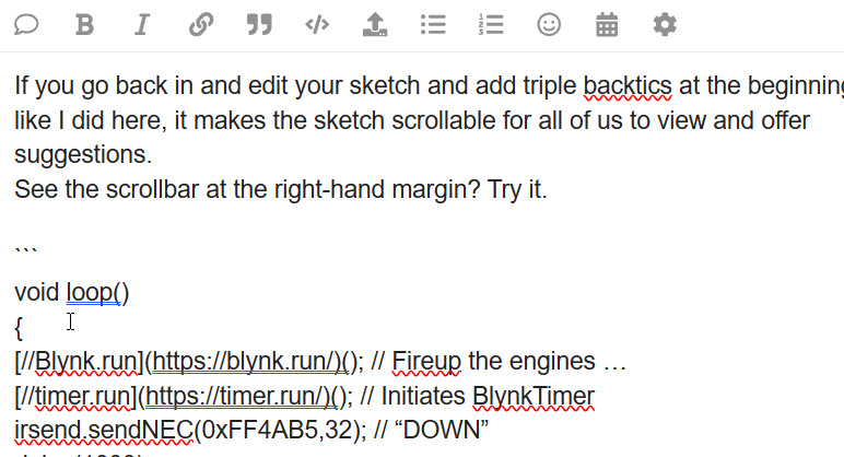
If you go back in and edit your sketch and add triple backticks at the beginning and end like I did here, it makes the sketch scrollable for all of us to view and offer suggestions.
See the scrollbar at the right-hand margin? Try it.
void loop()
{
[//Blynk.run](https://blynk.run/)(); // Fireup the engines …
[//timer.run](https://timer.run/)(); // Initiates BlynkTimer
irsend.sendNEC(0xFF4AB5,32); // “DOWN”
delay(1000);
}
(serial port debugging output)
10:46:34.574 ->
10:46:34.574 -> Blynk Online Message Broker (the BOMB)
10:46:34.608 -> Oasis Drive router
10:46:34.608 -> [261] Connecting to ATnT
10:46:37.635 -> [3304] Connected to WiFi
10:46:37.635 -> [3304] IP: 192.168.1.80
10:46:37.668 -> [3304]
10:46:37.668 ->     ___  __          __
10:46:37.701 ->    / _ )/ /_ _____  / /__
10:46:37.735 ->   / _  / / // / _ \/  '_/
10:46:37.769 ->  /____/_/\_, /_//_/_/\_\
10:46:37.802 ->         /___/ v0.6.1 on NodeMCU
10:46:37.836 ->
10:46:37.836 -> [3380] Connecting to blynk-cloud.com:80
10:46:37.869 -> [3566] <[1D|00|01|00]
10:46:37.972 -> [3665] >[00|00|01|00|C8]
10:46:37.972 -> [3665] Ready (ping: 98ms).
10:46:38.007 -> [3665] Free RAM: 48568
10:46:38.041 -> [3732] <[11|00|02|00]Hver[00]0.6.1[00]h-beat[00]30[00]
10:46:38.176 -> [3845] >[00|00|02|00|C8]
10:46:38.210 -> [3846] <[14|00|03|00|09]vw[00]19[00]clr
10:46:38.243 -> [3913] <[14|00|04|00]Fvw[00]19[00]
10:46:38.344 -> [3990] <[14|00|05|00|1A]vw[00]19[00]2020-0524[0D|0A|0D|0A]
10:47:08.147 -> [33846] <[06|00|06|00|00]
(telemetry starts here ---)
10:47:26.717 -> PX:0.03 PY:30.94 A:30.96  M1:1590.50 M2:0.00 M3:0.00 PAN:0.00
10:47:26.784 -> PX:1.01 PY:30.91 A:30.88  M1:1590.50 M2:-59.36 M3:0.00 PAN:0.00
10:47:26.851 -> PX:1.99 PY:30.83 A:30.80  M1:1590.50 M2:-58.74 M3:0.00 PAN:0.00
10:47:26.918 -> PX:2.96 PY:30.77 A:30.72  M1:1590.50 M2:-58.83 M3:0.00 PAN:0.00
10:47:26.986 -> PX:3.94 PY:30.68 A:30.63  M1:1590.50 M2:-58.93 M3:0.00 PAN:0.00
10:47:27.053 -> PX:4.91 PY:30.60 A:30.55  M1:1590.50 M2:-59.01 M3:0.00 PAN:0.00
10:47:27.121 -> PX:5.89 PY:30.52 A:30.47  M1:1590.50 M2:-59.11 M3:0.00 PAN:0.00
10:47:27.188 -> PX:6.87 PY:30.43 A:30.38  M1:1590.50 M2:-59.97 M3:0.00 PAN:0.00
10:47:27.258 -> PX:7.85 PY:30.35 A:30.30  M1:1590.50 M2:-59.30 M3:0.00 PAN:0.00
Cheers, Mike
Hi Mike, Thanks for the example.
I’ve tried adding the backticks to my sketch code but I’m still missing something. I’ve added them to the beginning and end of the entire code block and to various areas within the block but I am still doing something wrong as the scroll bars are not showing up in the post. Sorry for being so dense.
Do I have to save the sketch again after adding the backticks for this to work?
Here is a screenshot of my raw post, showing the 3 backticks at the beginning (and end) on separate lines; this works for me. There are plenty of people willing to help if you make it easier to scroll thru your code and USB “debug” runlog output.
Hit “Save” after done editing and the backticks should work.
Cheers, Mike
Here is a partial post of your stuff with backticks added.
I’ll let you go back in and properly edit your post and try again.
void sendtoBlynk() // In this function we are sending values to blynk server
{
Blynk.virtualWrite(VPIN_TOTAL_GALLONS, totalGallons); //replaced histgallons with totalGallons as 3rd test showed nothing on Blynk
Blynk.virtualWrite(VPIN_FLOW_RATE, flowRateGallons); // Displays the flow rate for this second in gallons / minute (G/min) ON V2
}

void setup()
{
Serial.begin(57600);

Blynk.begin(auth, ssid, pass); //Connect to Blynk
//ArduinoOTA.setHostname(OTA_HOSTNAME); // For OTA - Use your own device identifying name LK commented out to test wifi failure
//ArduinoOTA.begin(); // For OTA LK commented out to test wifi failure

pulseCount = 0;
flowRate = 0.0;
flowMilliLitres = 0;
totalMilliLitres = 0;
oldTime = 0;
totalLitresold = 0;
flowRateGallons = 0.0; //LK added this block to provide conversion rate from Liters to Gallons
totalGallons = 0;
totalgallonssold = 0;
histgallons = 0; //cumulative Gallons from Blink on V1 plus new volume

pinMode(PULSE_PIN, INPUT); // Initialization of the variable “PULSE_PIN” as INPUT (D2 pin)

attachInterrupt(PULSE_PIN, pulseCounter, FALLING);

timer.setInterval(10000L, sendtoBlynk); // send values to blynk server every 10 sec

//Start Wifi Connection LED Verification block===========
pinMode (D0, OUTPUT); //LK added to blink LED on board Lower LED near USB power port

digitalWrite(D0, LOW); //LK added to blink Lower LED near USB power port
//USE PUTTY SERIAL MONITOR APP ON PC TO SEE THIS TEXT
Serial.begin(57600);
Serial.println();
Serial.print("Wifi connecting to ");
Serial.println( ssid );

WiFi.begin(ssid,pass);

Serial.println();
Serial.print(“Connecting”);

while( WiFi.status() != WL_CONNECTED ){
delay(500);
Serial.print(“.”);
}
trying with backticks instead of periods
Are you confusing the backtick character with an apostrophe?
Are the three backtick characters at the left- hand margin of your code on a line all by themselves?
Here is the backtick on my keyboard beneath the tilda character:

No, I was using a period as the backtick…never used that character before in my life ![]()
Just tried again using the backtick character but still not having any luck.
Am I supposed to copy the backtick characters along with the code snippet before I paste it into the post body?
This just can’t be that hard.
Look at my raw code example. Just three backticks on a single line above the void loop(), and three final ones after the last code line all by themselves. Just go back and edit your earlier post and add the backticks before and after the code.
For all the years I’ve been here, there are only two rules.
Be friendly and use triple backticks. You’re almost there.
Cheers,
Mike
AAArrrgghhh!!! I was making it too difficult. I did as you suggested and updated my original post body with the backticks and it now shows the scroll bars.
The first time, I added periods instead of backticks which is why it didn’t work then.
The rest of the time I had misunderstood and was adding the backticks to the actual Arduino Cloud Sketch code and just couldn’t understand why it wasn’t working.
Thanks for having so much patience with me and sorry for taking up so much of your time.
I’m at lunch so I had time to cruise the board. I saw this as an easy solution to get you up and formatted again. I’ll let @PeteKnight grab the control stick and resume working with you. If I see anything else to add, I’ll chime in. Out of here in 6 minutes.
Cheers,
Mike
Pete, I finally got the backtick thing worked out with Mike and updated my post so it should now have the right formatting.
Thanks to you I also found the Monitor on the Arduino Cloud UI and have it working too, so no more puTTY.
I REALLY appreciate your help.
Unfortunately while I was doing this I also re-flashed the ESP8266 and while it shows it is connecting to my wifi, it is failing to connect to Blynk.
It keeps repeating the following in the monitor:
{ll��|�$�|
�l�b|�����|#�
"��on�lNo���
#
p��#$`r$p�n��l��
bo�|l�
�b��No�$��l �2no
$`N{���n
b
�$r��n
b
�l�l�p���� ��o�[61] Connecting to NETGEAR82
[4563] Connected to WiFi
___ __ __
/ _ )/ /_ _____ / /__
/ _ / / // / _ \/ '_/
/____/_/\_, /_//_/_/\_\
/___/ v0.5.8 on NodeMCU
[4570] Connecting to blynk-cloud.com:80
[9571] Connecting to blynk-cloud.com:80
[14572] Connecting to blynk-cloud.com:80
[19573] Connecting to blynk-cloud.com:80
Any ideas?
Okay, that makes sense now. You’d previously referred to flashing via s “cloud connection” when you actually meant via a wired connection, which was the source of the confusion. Thanks for clarifying/correcting.
It looks like you have the Blynk for Chinese library installed. This isn’t compatible with Blynk IoT and you need to delete it and ensure that you have the latest Blynk IoT C++ library installed. The current version is v1.3.2
The rest of your code is a mess though.
You shouldn’t be doing any of this…
and none of this should be 8n your void loop…
I’m very surprised that you aren’t getting “ISR not in IRAM” runtime errors and reboots because of the way that your interrupt IRS is defined. I suspect that this is because you are using a very early version of the ESP8266 core, which will ultimately cause you other issues.
It’s always best to be running the latest core, which is currently v3.1.2 bit tgat will then require you to fix your ISR issue.
Pete.