Hello. I have 2 led strips, one is rgb(24v) and the other is a single color(12v). I’m using a nodemcu with 3 TIP120 transistors to change the colors using the blynk app. I’d like to be able to control the single color strip with the same nodemcu, without adding an extra power source for this strip. Is it possible to limit the voltage received by using another TIP120 transistor? It might sound stupid, but let’s say the maximum intensity of the rgb strip is achieved at the slider value of 1023, does the rgb strip receive half voltage at the value of 512?
Yes and no. You won’t get half the voltage but it will probably safely do what you want.
LEDs are current, not voltage, dependent. If you use an analog output, setting the output to half it’s maximum will will switch between 24V half the time and 0V the other half of the time, at a high frequency. (This is called Pulse Width Modulation or PWM.) This will result in an average current of half of what you would get if the LEDs received a constant 24V (which is the same total current the LEDs would receive at a constant 12V). Therefore, as long as you’re not exceeding the maximum pulse current rating for the LEDs, it should be safe and work as desired.
However! Note that if you ever exceed the 50% output setting, you will be feeding higher than the average current equivalent of a 12V constant current, which could damage the LEDs. Also, if you accidentally set the output as a digital output and set it so the transistor is always on, you would end up with a constant 24V to the LEDs and likely destroy them. Don’t say I didn’t warn you if you accidentally blow your 12V strip attempting you use this technique.
Well, I’m planning to use a button widget for a dgitial pin with the off value = 0 and the on value <512, maybe around 500. //Or maybe using a virtual pin
That doesn’t make sense. A button widget sends a 1 or 0 to the hardware. The software running in the hardware has to receive this input and use it to control a physical pin.
A digital pin, set as an output, can only be set to on or off (high or low). You need to use a pin set for analog output, to set PWM values between a minimum and maximum range.
So as I said, I have an rgb strip with each color linked to a transistor and to a digital pin. In the app I use sliders to go from 0 to 1023 to control intensity. I have tried using a button and indeed, setting the values to 0 and 1 means off(0)and 1023(1, max value). BUT if I choose the values as 0 and anything > 1(I tried with 2 and 512) the leds are set to the corresponding intensity
Where are you choosing these values?
Edit: Sorry, I understand now. I thought that a button widget only sent 0 or 1. I didn’t know that you could set other “pressed” and “released” values for a button.
In the button widget. I’ll atach a video
As you can see, when the button is set to 0 and 1 the slider doesnt move, but I can tell you that the leds are at maximum intensity. However, if I choose another value as shown in the video, the slider moves to the respective value and the leds to the respective intensity
//so, using this method I will theoretically be able to achieve what I’m trying to, right?
Yes, I edited my previous post while you were replying.
This should work but note that, on an ESP8266, analog output on a pin using PWM is done in software (there’s no hardware PWM controller). If anything goes wrong with the software which ends up halting the control of the pin and it ends up stuck in the “on” state, it will put a constant 24V on your LED strip.
I understand, I will probably use a virtual pin that will automatically trigger the value of the digital pin when is on. Would I also be able to achieve this by adding an ~10k resistor when powering the led? Also, the circuit would be the same as to the rgb strip, with the cathode of the led strip connected to the transistor? (As I’ve seen rgb strips with both common anode and common cathode)
No. You want to be switching the transistor fully on or off, feeding either 24V or 0V to the LED strip and using PWM to create an average current. Using a resistor to drop the voltage to 12V wastes half your energy as heat in the resistor or transistor, and the resistor value could be difficult to calculate.
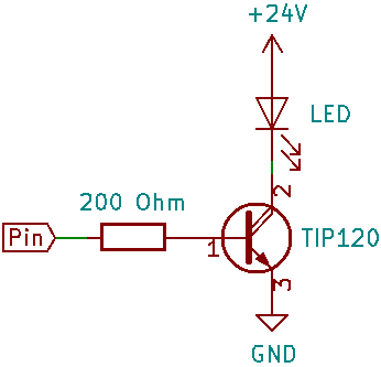
I think so. Tell me exactly how you’ve got the transistors and LED strip(s) wired now. (Post a schematic, if possible.)
This would be it

//I also have some resistors and diodes between the pins and the transistor as the first nodemcu I used completely failed, but that board might’ve been faulty from the beggining
Note that in your above fritzing diagram, the wiring of the collector and emitter of your “blue” transistor is reversed.
As you found out, you need a resistor between the NodeMCU output pin and the base of each transistor to limit the current from the pin into the base. Otherwise you could damage the pin. I think 100 200 Ohms would be about right for this application. You shouldn’t need any diodes.
Yes, it should be.
100 Ohms might be a bit low for the current capability (12mA) of an ESP8266 pin. What is the maximum current that your LED strips will draw for each colour? As long as it’s less than 2A, I think 200 Ohms would be a better resistor value.
(I’ve edited my previous post.)
I think for this type or circuit, you would also need a suitably selected capacitor to act as a buffer, which could then theoretically, provide a steady 12v feed.
No, a capacitor shouldn’t be necessary as long as you don’t exceed the peak forward current for the duty cycle you’re using. You would have to look at the datasheet for the LEDs you’re using to be sure, but offhand I don’t think this will be a problem with only double the rated steady current.
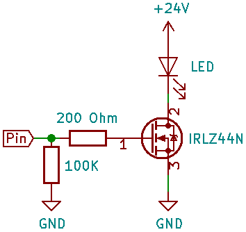
The IRLZ44N is a MOSFET whereas the TIP120 is a darlington transistor. Either will work fine for your purpose. The MOSFET can handle more current and will have a lower voltage drop across it, so it will run a slight bit cooler and more efficiently. It will also provide far less current loading on the pin driving it.
For the MOSFET, you should still include a resistor between the pin and the gate (for a different reason than the transistor) but you should also add a second resistor between the pin and ground to prevent the MOSFET turning on when the pin is high impedance (before initialisation).
Resistor values aren’t as critical here and could be changed somewhat.
I use tip120 for the rgb strip and they seem to work fine without a resistor connected to the ground. Maybe that is because they are made for 24v.
I am currently trying the circuit with a led strip sample made to run at 12v. I keep it at half value but it seems to heat up pretty fast and pretty bad, especially where the connection is made… any idea what value should the current have? And where should I measure
As I said, the TIP120 is a darlington. It doesn’t need a resistor to ground. The resistor to ground is only needed for a MOSFET.
What heats up, the transistor or the LED strip?
That would be given in the specifications for the LED strip.
You can measure the current either between the power supply and the LED anode or between the LED cathode and the transistor collector. You need to break the connection and insert an ammeter.
the led strip heats up. I’m not sure what the specs of the strip are, but on the supply I used before it says max 500mA. Also, the strip buzzez between the values of 0-500