Blynk Libraries

I spent a day or more debugging an Arduino sketch that was constantly disconnecting and reconnecting to the Blynk servers. In the end I tracked it down to passing an integer, rather than the required string, to the LCD.

I suspect over the last few weeks I have had other errors in my code that have caused similar problems. Would it be possible for the Blynk libraries to check for these errors like the Arduino IDE does?

Even some error message from the server would be better than a simple disconnect and reconnect.

@Pavel @Dmitriy @vshymanskyy

The image above shows the immediate disconnects from the Blynk server as identified by the Serial data below (edited out pwd and part of auth):

[115] Blynk v0.3.3-beta
...........
[3688] Connected to WiFi
AT+CIPCLOSE
AT+CIPCLOSE
AT+CIPSTART="TCP","cloud.blynk.cc",8442
AT+CIPSEND=37
    8cb0a1931a1a402881cf348f0a5xxxxx[14161] Ready (ping: 12ms).
AT+CIPSEND=108
   gver 0.3.3-beta h-beat 10 buff-in 256 dev Arduino cpu ATmega328P con ESP8266 build Jan 19 2016 11:27:51 AT+CIPCLOSE
[24450] Login timeout
AT+CIPCLOSE
AT+CIPCLOSE
AT+CIPCLOSE
AT+CIPSTART="TCP","cloud.blynk.cc",8442
AT+CIPSEND=37
    8cb0a1931a1a402881cf348f0a5xxxxx[39994] Ready (ping: 12ms).
AT+CIPSEND=108
   gver 0.3.3-beta h-beat 10 buff-in 256 dev Arduino cpu ATmega328P con ESP8266 build Jan 19 2016 11:27:51 AT+CIPCLOSE
[50284] Login timeout
AT+CIPCLOSE
AT+CIPCLOSE
AT+CIPCLOSE
AT+CIPSTART="TCP","cloud.blynk.cc",8442
AT+CIPSEND=37
    8cb0a1931a1a402881cf348f0a5xxxxx[65830] Ready (ping: 12ms).
AT+CIPSEND=108
   gver 0.3.3-beta h-beat 10 buff-in 256 dev Arduino cpu ATmega328P con ESP8266 build Jan 19 2016 11:27:51 AT+CIPCLOSE
[76869] Login timeout
AT+CIPCLOSE

As you will see there are constant ‘timeouts’ and this is confirmed on the Android with repeated messages as per the image. I think I have traced the issue down to the following piece of code:

void reconnectBlynk() {    // disabled at present

  if (!Blynk.connected()) {  // if not connected
    if(Blynk.connect()) {    // try to reconnect
      digitalWrite(GreenLED, HIGH); // turn LED ON
      //Blynk.notify(" Reconnected to Blynk");
      Serial.println(" RECONNECTED to Blynk server.");
      delay(100);
    } else {
      digitalWrite(GreenLED, LOW); // turn LED OFF
      //Blynk.notify(" Disconnected from Blynk");
      Serial.println(" FAILED to reconnect to Blynk server.");
      delay(100);
      
      Blynk.begin(auth, wifi, "GargoyleTest", "19651965AB");
      while (Blynk.connect() == false) {
        // Wait until connected
      }  
      // resetFunc();  // reset Arduino
    }
  }
}

This function is not even called as the 5 minute timer associated with it is commented out but I guess it is being read by your servers as a possible function. For reference the function is before the main loop() but it is just the same after the loop(). If I comment out the function my device connects ok to your server.

  1. What is wrong with the function?
  2. Can you please provide more than ‘timeout’ errors when we have ‘bugs’ in our code.

I’m sure I have noticed other issues where the server will disconnect without any given reason. For example write’s to the LCD such as:

  String CurrentTime = "5";
  lcd.print(0, 1, CurrentTime);  
  lcd.print(5, 1, "Minute(s)");

will cause constant disconnects and reconnects, whereas the following is acceptable:

  String CurrentTime = "5 Minutes(s)";
  lcd.print(0, 1, CurrentTime);  
  //lcd.print(5, 1, "Minute(s)");

What is wrong with the first version of the write to the LCD and can your libraries highlight our errors rather than just disconnecting us from the server?

@Costas Please put full sketch.

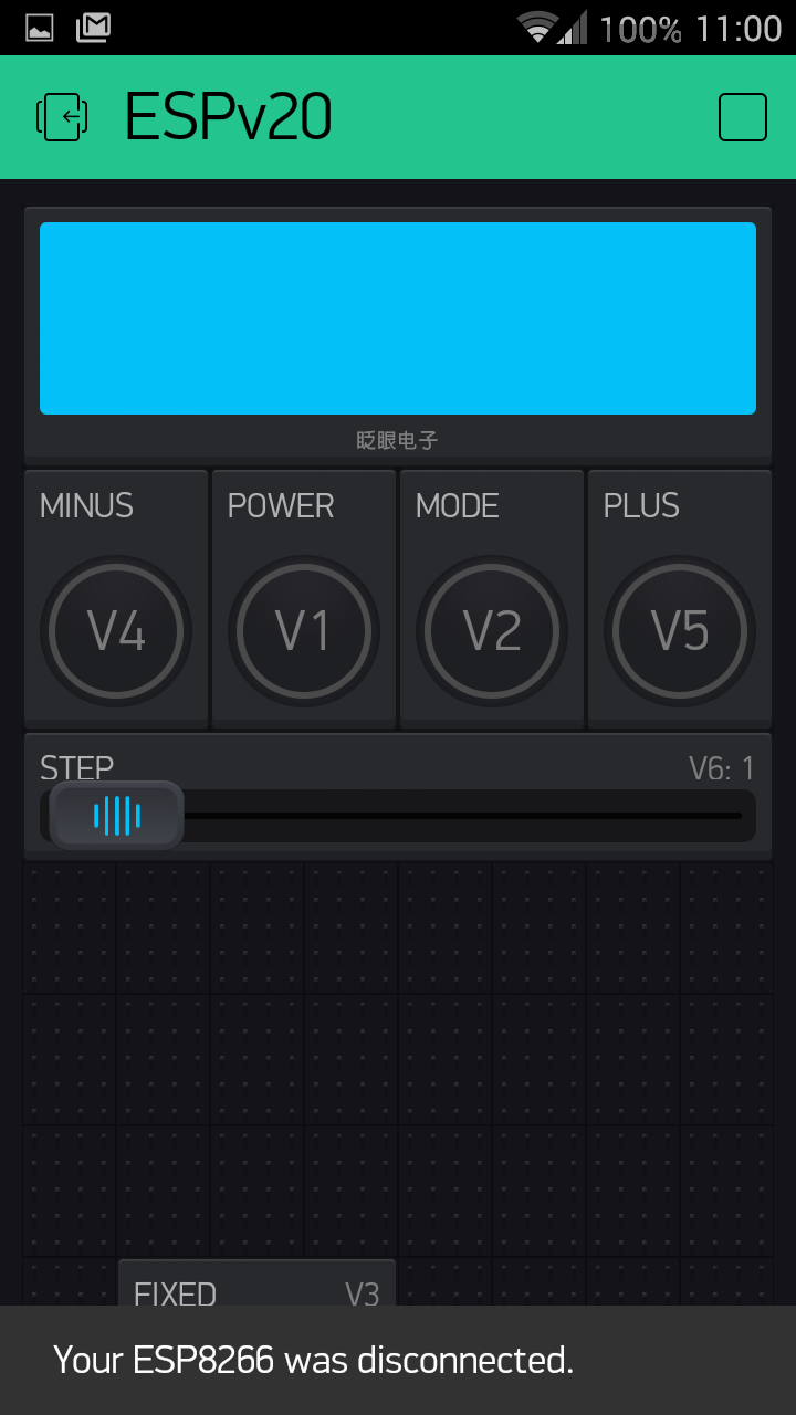
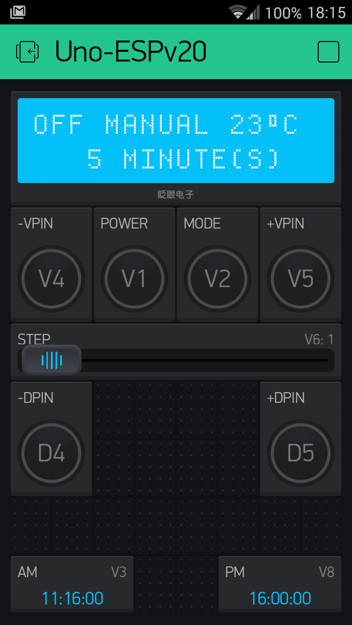
@Dmitriy full sketch below. The problem area is in BLYNK_WRITE(V5) from row 197. You will see many of the lcd.print commands are commented out as they crash the system with them in.

  //#define BLYNK_DEBUG
  #define BLYNK_PRINT Serial    // Comment this out to disable prints and save space
  #include <ESP8266_HardSer.h>
  #include <BlynkSimpleShieldEsp8266_HardSer.h>
  #include <avr/wdt.h> // watchdog timer, maybe set at 4 seconds in the sketch
  #include <EEPROM.h>
  int address = 100;  // first EEPROM address
  int MemoryValue; // EEPROM value for calibrating temperature sensor
  
  #define EspSerial Serial // Set ESP8266 Serial object
  ESP8266 wifi(EspSerial);
  
  char auth[] = "8cb0a1931a1a402881cf348f0axxxxx";

  WidgetLCD lcd(V0);
  byte GreenLED = 2; // green led on pin 2
  byte CentralHeating = 0;
  byte ModeCount = 0 ; // select different modes of operation
  // RF Variables
  int rfsignal = 0;  // variable to count number of signals received, maximum 200
  int timeDelay = 105;    // The variable used to calibrate the RF signal lengths.
  #define rfTransmitPin 10 // digital 10  //RF Transmitter pin - THIS IS FOR CHEAP TRANSMITTER DVG
  // see also VirtualWire message transmit pin set the same at row 82
  #define voltagePin 9
  #define groundPin 8

  #include <OneWire.h>
  #include <DallasTemperature.h>
  // Data wire is plugged into pin A3 on the Arduino
  #define ONE_WIRE_BUS A1  // was 3 digital now analogue pins
  // Setup a oneWire instance to communicate with any OneWire devices (not just Maxim/Dallas temperature ICs)
  OneWire oneWire(ONE_WIRE_BUS);
  // Pass our oneWire reference to Dallas Temperature. 
  DallasTemperature sensors(&oneWire);
  #define TempvoltagePin A0
  #define TempgroundPin A2
  int TempNow = 0;
  String TempSuffix = "ºC";  // remember create separate strings before trying to print or write them to Blynk
  //String TimeSuffix = " Minute(s)";
  String TimePrefix = "   ";
  String CurrentTemp;
  String CurrentTime;
  int Calibrate = 91; // percentage to calibrate temperature sensor to real temperature
  byte TimerStarted = 0;
  int CountdownTime = 0; // number of minutes for time to countdown 
  int STEP = 1;  // default timer STEP adjustment on Pin V6 is 1 minuute (can be set from 1 to 20 minute steps)
 
  #include <SimpleTimer.h>
  SimpleTimer timer;

void setup()
{

   pinMode(GreenLED, OUTPUT); // set D2, green LED, as output
   digitalWrite(GreenLED, LOW); // turn green LED OFF
   pinMode(TempgroundPin, OUTPUT);
   digitalWrite(TempgroundPin, LOW);
   pinMode(TempvoltagePin, OUTPUT);
   digitalWrite(TempvoltagePin, HIGH);   
   pinMode(groundPin, OUTPUT);
   digitalWrite(groundPin, LOW);
   pinMode(voltagePin, OUTPUT);
   digitalWrite(voltagePin, HIGH);
   pinMode(rfTransmitPin, OUTPUT);   //Transmit pin is an output    
   //pinMode(SwitchPin, INPUT_PULLUP); // set D5 as input but set high when not pressed

   sensors.requestTemperatures();  // start temperature sensor
   Serial.begin(9600); // Set console baud rate
   delay(10);
   timer.run(); // Initiates SimpleTimer
   timer.setInterval(2000L, refreshLCD); // refresh LCD if needed every x seconds
   timer.setInterval(40000L, sendTemp); // send current temperature to lcd V0 every 40 seconds
   timer.setInterval(60000L, CheckTimer);  // check timer every 60 seconds(EVERY MINUTE)
      
   
   EspSerial.begin(115200); // Set ESP8266 baud rate
   delay(10);

   Blynk.begin(auth, wifi, "GargoyleTest", "xxxxx");
   
   while (Blynk.connect() == false) {
    // Wait until connected
   }
   // all Blynk stuff must be done AFTER connection
   lcd.clear();  
   lcd.print(0, 0, "OFF");
   TempNow = (((sensors.getTempCByIndex(0)* Calibrate)*1)+50)/100; // 50 is for rounding
   CurrentTemp = TempNow + TempSuffix;
   lcd.print(11, 0, CurrentTemp); // display temperature on line 0 from character 11    
   lcd.print(3, 1, "0 Minute(s)");   // set initial lcd details for manual mode on second row
   NEWtransmitFixedCode();   // turn system off on restart
   wdt_enable(WDTO_8S);  // set WDT to 8 seconds
   MemoryValue = EEPROM.read(address);
   if ((MemoryValue > 79) && (MemoryValue < 121)){
      //Serial.print(" Calibration value is ");  // change this to LCD
      //Serial.println(MemoryValue, DEC);
      Calibrate = MemoryValue;
   }
   else{
      // EEPROM will only be updated if value for Calibrate changes
      EEPROM.update(address, Calibrate);   // if no value in address 0 write 95 % calibration percentage    
      delay(20);
   }  
}

void(* resetFunc) (void) = 0; //declare reset function @ address 0 THIS IS VERY USEFUL


BLYNK_WRITE(V1) // reads virtual push button V1 but only when it is pressed
{               // this is main ON / OFF button
  int VSwitch = param.asInt();    // read V1
  if (VSwitch == 1){  
      if (CentralHeating == 0){   // central heating was off so turn it on
        HeatingOn();
      }
      else{     // central heating was on so turn it off
        HeatingOff();
        TimerStarted = 0; // switch off timer if it was on
      }    
  NEWtransmitFixedCode();
  }
}

BLYNK_WRITE(V2) // reads virtual push button V2 but only when it is pressed
{               // this is mode / timer button
  int V2Switch = param.asInt();    // read V1
  if (V2Switch == 1){
    if (ModeCount == 0){
      lcd.print(0, 1, " PLUS to Change ");
      ModeCount++;  // only needed once to prompt for PLUS button Mode menu
    }
    else{  // PLUS button has been pressed at least once so start using the new mode
      lcd.print(0, 1, " POWER to Start");
      ModeCount = 0;  // clear ModeCount so LCD will go back to refreshing
    }

  }
}

BLYNK_WRITE(V3) // Widget is reading AM timer on V3
{
  int AMTimer = param.asInt();
  if (AMTimer == 1) {
    HeatingOn();    
  }
  if (AMTimer == 0) {
    HeatingOff();   
  }
  NEWtransmitFixedCode();
}


void intsize(){  // no negatives for time but there can be for temperature to -99 degrees
                    // valLen not currently needed
  if(CountdownTime > 999){
    TimePrefix = "";
  }
  else if(CountdownTime > 99){
    TimePrefix = " ";
  }
  else if(CountdownTime > 9){
    TimePrefix = "  ";
  }
  else if(CountdownTime < -9){
     TimePrefix = " ";
  }
  else if(CountdownTime < 0){
     TimePrefix = "  ";
  }
  else{
    TimePrefix = "   ";
  }   
}


BLYNK_WRITE(V4){ // widget for MINUS time or temperature
  int MinusBtn = param.asInt();
  if (MinusBtn == 1){
    if (CountdownTime > 0){
        CountdownTime = CountdownTime - STEP;
    }
     else{
        CountdownTime = 1440; // reset minutes from 0 to 1440
     } 
    intsize();
    CurrentTime = TimePrefix + CountdownTime;
    Serial.println();
    Serial.println(CurrentTime);
    //lcd.clear();  // this crashes the system, why?
    lcd.print(0, 1, CurrentTime); 
   }
}

BLYNK_WRITE(V5){ // widget for PLUS time or temperature
  int PlusBtn = param.asInt();
  if (PlusBtn == 1){
    if (ModeCount == 0){  // only increase time if not in mode change
      if (CountdownTime < 1440){
           CountdownTime = CountdownTime + STEP;
      }
        else{
          CountdownTime = 0; // reset minutes from 1440 to 0
        }
      intsize();
      CurrentTime = TimePrefix + CountdownTime;
      //lcd.print(0, 1, CurrentTime);
    }
    // different modes
    if(ModeCount > 0){
      ModeCount++; 
      if(ModeCount == 2){  // timer mode 
        //lcd.print(0, 1, " Countdown Mode");
        //lcd.print(10, 0, "MODE1");   // why ok to write to row 0 but not row 1?
     /*
        if (CountdownTime > 0){  // only activate timer if 1 or more minutes set
          TimerStarted = 1;
          HeatingOn();
          NEWtransmitFixedCode();
        }
        else{
          lcd.print(0, 1, "  Press - / +   ");
        }
     */
      }
      
      else if(ModeCount == 3){  // thermostatic mode
        //lcd.print(0, 1, "  Thermostat    ");
        //lcd.print(10, 0, "MODE2");
      }
      else if(ModeCount == 4){  // other mode for calibrate / restart etc
        //lcd.print(0, 1, "  Other         ");
        //lcd.print(10, 0, "MODE3");
      }
      else{
        ModeCount = 0;  // reset back to manual mode
        //lcd.print(0, 1, "  Manual Mode   ");
        //lcd.print(10, 0, "MODE0");
      }   
  }
 }
}

BLYNK_WRITE(V6) // reads STEP on V6 pin, range 1 to 20 minutes
{
  STEP = param.asInt(); // reads STEP on V6 pin
}


void HeatingOn(){   // details for heating on
    CentralHeating = 1;
    digitalWrite(GreenLED, HIGH); // turn LED ON
    lcd.print(0, 0, "ON ");
}

void HeatingOff(){    // details for heating off
    CentralHeating = 0;
    digitalWrite(GreenLED, LOW); // turn LED OFF
    lcd.print(0, 0, "OFF");    
}

void NEWtransmitFixedCode() {

  int deviceFixedAction[28] = {28,18,3,3,11,3,11,3,11,3,11,3,11,11,3,3,11,3,11,11,3,3,11,11,3,11,3,413}; // FixedAction array for OFF
  if (CentralHeating==1) {
    deviceFixedAction[24] = 11;
    deviceFixedAction[23] = 3;
    deviceFixedAction[22] = 3;
    deviceFixedAction[21] = 11;  // only these 4 array items need changing for OFF to become ON    
  }
  rfsignal = deviceFixedAction[0];
  int repeats = deviceFixedAction[1];
  //The signal is transmitted several times in succession - this may vary with your remote, repeats holds this variable.
  for(int j = 0; j<repeats; j++){
    for(int i = 2; i<rfsignal; i=i+2){    // signal starts at position 2 in the array, 0 is overall size of the array, 1 is the number of repeats
      digitalWrite(rfTransmitPin, HIGH);   // Transmit a HIGH signal
      delayMicroseconds(deviceFixedAction[i]*timeDelay);
      digitalWrite(rfTransmitPin,LOW);  // Transmit a LOW signal
      delayMicroseconds(deviceFixedAction[i+1]*timeDelay);
    }
  }
}

void refreshLCD(){  // refresh LCD every x seconds but use last temperature reading not new one
    lcd.print(11, 0, CurrentTemp); // display temperature on line 0 from character 11
    if (ModeCount == 0){   // only refresh row 2 if mode is not being changed
      CurrentTime = TimePrefix + CountdownTime;
      CurrentTime = CurrentTime + " Minute(s)";
      lcd.print(0, 1, CurrentTime);  
      //lcd.print(5, 1, "Minute(s)");  // this will crash the system, why?
    }
    if (TimerStarted == 0){   // don't change status if timer has been activated
      if(CentralHeating == 1){
        lcd.print(0, 0, "ON ");
      }
      else{
        lcd.print(0, 0, "OFF");      
      }
    }
    else{
      lcd.print(0, 0, "ON ");  // timer running so show ON
    }  
}

void sendTemp()   // display current temperature every 40 seconds plus status and minute(s) on LCD
{                 // status and minutes are added in case the screen has cleared in error
    sensors.requestTemperatures();
    TempNow = (((sensors.getTempCByIndex(0)* Calibrate)*1)+50)/100; // 50 is for rounding
    CurrentTemp = TempNow + TempSuffix;
    lcd.print(11, 0, CurrentTemp); // display temperature on line 0 from character 11
}

void CheckTimer()   // every 60 seconds check if timer is still running
{
  if (TimerStarted == 1) {
   if (CountdownTime >=1){
     CountdownTime--;
     intsize();
     CurrentTime = TimePrefix + CountdownTime;
     lcd.print(0, 1, CurrentTime);
   }
   if (CountdownTime == 0){
      //Blynk.notify(String(" Central Heating Timer Just Ended"));
      TimerStarted = 0;
      intsize();
      CurrentTime = TimePrefix + CountdownTime;
      lcd.print(0, 1, CurrentTime);
      lcd.print(0, 0, "OFF");
      HeatingOff();
      NEWtransmitFixedCode();        
   }
 }  
}

void loop()
{
  Blynk.run();
  timer.run(); // Initiates SimpleTimer
  wdt_reset(); // if we get here turn off 8 second WDT
}

@vshymanskyy maybe you see something strange?

First of all, is the simple Blynk example sketh working with your setup?
It looks like you may have problem in your wiring.
What arduino board do you use? is in Nano/UNO?

@vhymanskyy yes the example sketches work fine, no problem with the wiring.
Technically they are Nano’s with ESP but the Nano’s have a WDT bug so they are uploaded as Uno’s.

It is a known problem that ESP in AT mode is hard for Arduino to handle. Maybe your sketch is making “sending data bursts”, in this case it can loose some data and cannot synchronize anymore.
BTW, could you try switching to library v0.3.1.
It has a different login procedure, this might help. We’ll check v0.3.3 then.

@vshymanskyy just to add I can connect Ok with the Nano as Uno with ESP but your servers kick me out when I start sending write’s to the LCD. I can actually flood the LCD write’s every half second over and over again without problem. When I ask for a simple LCD write with a button push (V5 in the sketch) that is when your servers disconnect me.

@vshymanskyy @Dmitriy I think I am close to resolving the problem. The Arduino has no problem with writes to the LCD based on a timer at 0.1 second intervals so it can easily cope with the ‘load’.

I think I have isolated the problem down to the temperature sensor I have hooked up to the Arduino.
As you may know it takes a relatively long time to read the temperature on an Arduino but I don’t think this is the problem.

The pin definitions for the temperature sensor are tied to the analogue pins (the definitions and pinMode’s are shown below):

  #define TempvoltagePin A0
  #define ONE_WIRE_BUS A1
  #define TempgroundPin A2

   pinMode(TempgroundPin, OUTPUT);
   digitalWrite(TempgroundPin, LOW);
   pinMode(TempvoltagePin, OUTPUT);
   digitalWrite(TempvoltagePin, HIGH);

It is a bit naughty of us to use the analogue pins to provide 5V to the temperature sensor but it means the sensor just plugs straight into the breadboard without any wires. My system fails even without the temperature sensor plugged into the breadboard if I still make calls to the sensor in the sketch.

So I see it as 2 possible issues:

  1. Either the ESP is failing because of the power allocation to the temperature sensor on analogue pin A0

or

  1. Blynk is somehow confused by the pin settings even though I don’t have any analogue (or digital at present) pins in the app. They are all virtual pins.

I guess I am favouring 1) as the problem but the reason I feel it could be 2) is that pressing the virtual buttons with the temperature sensor code in place seems to bring about the system crash. I will keep testing here but I just wondered if your system is confused by strange analogue pin definitions on our hardware even though they don’t appear in the app?

I think no. If no pin in app. - no confusion. But only @vshymanskyy may answer for sure.

Did you try hosting a local server instead of using the official Blynk server? That way you can start isolating the problem.

From my playing around with an ESP-01, I know it needs its own dedicated supply (it can pull enough current when needed). If it doesn’t have enough juice, it can lead to strange and random transmission errors.

Also, the ESP doesn’t handle bursts very well from what I’ve seen, can you pace the data instead of sending it in a burst?

@cyberbum it looks like the only way I will sort out the issue is to try a local server. I actually have ESP-12’s or something like and they run very well. I can flood the LCD and it works fine but a single press of a virtual button to write to the LCD can crash the system.

If you try with a local server, you can also call its REST api directly to simulate your button presses, so you can also isolate out the Android/iOS app.

The API can be found here:
http://docs.blynkapi.apiary.io

I already used this to trigger buttons without needing to run the apps.

@vshymanskyy I am VERY interested to know how your server handles pins.

In setup() I have a call to read a temperature sensor with the ‘strange’ pin assignments I have described.
I am currently running the system without the temperature sensor attached so there are no further calls to the sensor other than in setup().

Almost without fail if I press a virtual PUSH button your server disconnects me and reconnects. My device is not rebooting it is simply dropping the connection.

The line in setup() is sensors.requestTemperatures(); // start temperature sensor

The virtual push buttons in question are not tied to the temperature sensor, they simply increment a counter on the virtual LCD by 1. I also have an identical digital push switch that is included as a call from the main loop(). If I press the digital switch in the app your server does not disconnect me.

The 2 virtual buttons that are crashing the system are V4 and V5 however I do have 2 other virtual push buttons, V1 and V2 and they do not crash the system. V1 and V2 actually do more local processing than V4 and V5 as they write to the LCD and send an RF signal.

Below is the code and functions for V4:

BLYNK_WRITE(V4){ // virtual push switch on V4
  int MinusBtn = param.asInt();
  if (MinusBtn == 1){
    minustime();
  }
}

void minustime(){ // converts integer to string and pads with leading spaces based on length of integer so LCD is left formatted
      if ((CountdownTime - STEP) > 0){
        CountdownTime = CountdownTime - STEP;  // increase a counter
      }
      else{
        CountdownTime = 1440; // reset minutes from 0 to 1440
      }
      displaylcd();
}

BLYNK_WRITE(V6) // Slider reads STEP on V6 pin, range 1 to 60 minutes
{
  STEP = param.asInt(); // reads STEP on V6 pin
}

void displaylcd(){
      intsize();  // determines number of digits in the integer
      CurrentTime = TimePrefix + CountdownTime; 
      lcd.print(0, 1, CurrentTime);  
}

void intsize(){  // no negatives for time but there can be for temperature to -99 degrees
  if(CountdownTime > 999){
    TimePrefix = "";
  }
  else if(CountdownTime > 99){
    TimePrefix = " ";
  }
  else if(CountdownTime > 9){
    TimePrefix = "  ";
  }
  else if(CountdownTime < -9){
     TimePrefix = " ";
  }
  else if(CountdownTime < 0){
     TimePrefix = "  ";
  }
  else{
    TimePrefix = "   ";
  }   
}

If I comment out the single row in setup() and make it:

//sensors.requestTemperatures(); // start temperature sensor

V4 and V5 work fine.

@Dmitriy thinks your server only knows about pins that I define in the app but the strange behaviour above indicates you are checking all the pins or that your virtual pins have a serious bug. Just to reiterate a digital push switch called from loop(0), with the same code as V4 or V5 is fine but V4 and V5 are unusable.

@vshymanskyy a screenshot for you.

Down the left side of the screen I have -VPIN and -DPIN and down the right hand side +VPIN and +DPIN.

Ironically now that I have added a second digital pin for the problematic pins it has almost fixed the virtual pins issue. The void loop now looks like this:

void loop()
{
  Blynk.run();
  timer.run(); // Initiates SimpleTimer
  CheckMinusSwitch(); // Check to see if D4 switch has been pressed
  CheckPlusSwitch(); // Check to see if D5 switch has been pressed
}

By having the second digital pin in the loop() it slows down access to your virtual pin loop just enough for the virtual pins to work as they should. This is not a solution as it depends on too many factors and guesswork to slow down your virtual pins.

Can you please check your code and see how your virtual pins differ from your real pins? They obviously need to perform the same whether they are virtual or real.