Perhaps this may a little premature as I just got the code to a working state as of this morning, but this project is just a part of my larger project and will be grafted in as soon as I can. However, this can be a stand alone project to be used in a variety of ways. The way I’ve configured my app is to select which pump, how much (in milliliters) it will dose out and a button to set everything into motion. I am also using a Terminal Widget to be used the same way as an LCD or Serial Monitor would otherwise.
My usage of this project is for dosing precise amounts of nutrient solutions into water for hydroponics gardening. However, this project can easily be used to mix cocktails or even mix paint in an auto body shop. I presume this project would be useful in many applications involving small precise dosing of liquids/fluids.
Before I move on, I must thank the fellow Blynker (@Fettkeewl) for pretty much holding my hand and walking me through the construction of the code, as well as his enuring patience as we debugged my VERY many mistakes along the way. I see his presence on many other threads doing the same, helping helping helping. He is without question a very commendable man!
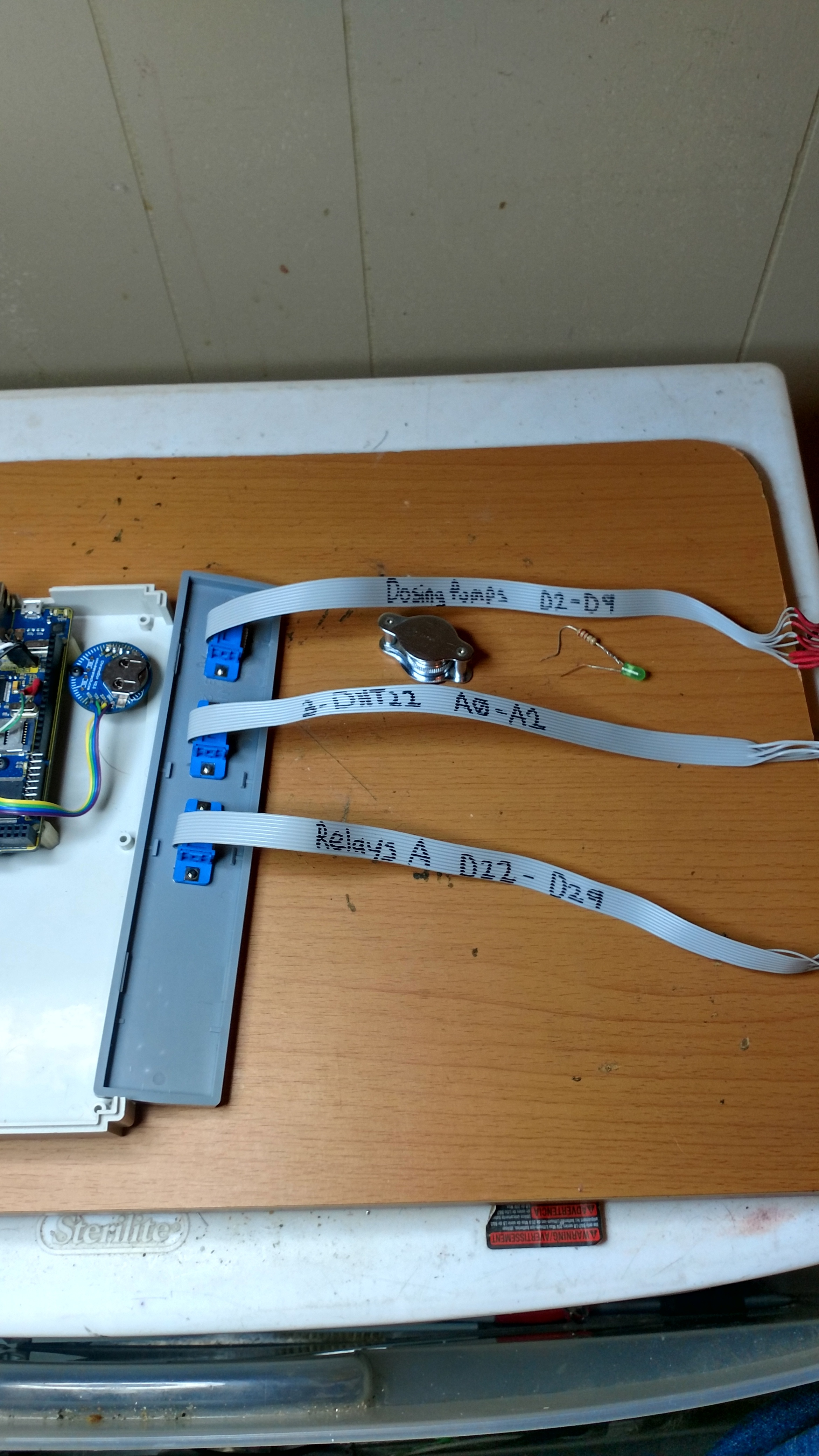
That said, I will share this project in as much details as I have. When constructing the circuitry, I took a few pictures, plus the videos on YouTube and sketches, I think it should be a decent collection of information for someone else to use and improve upon.
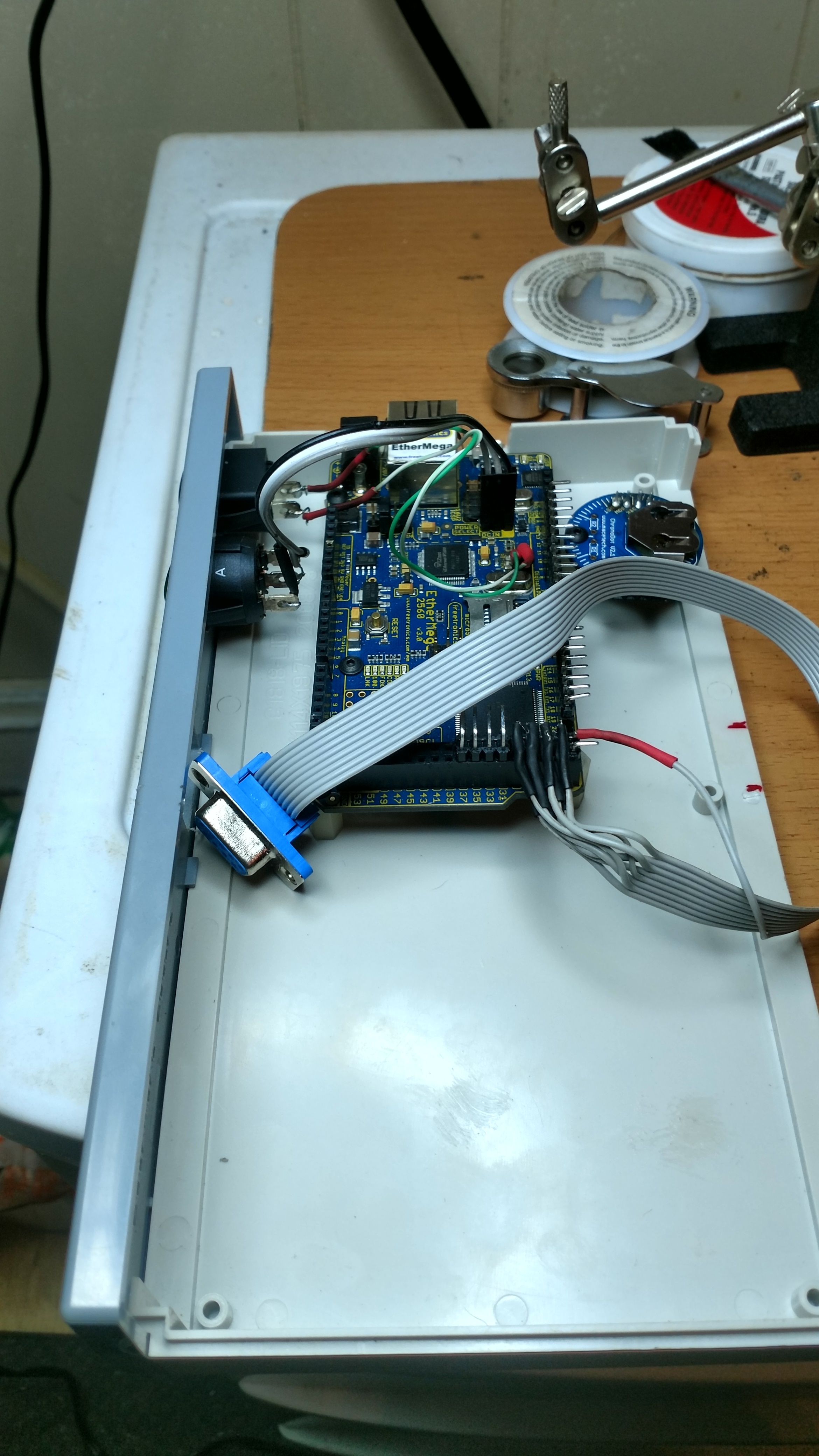
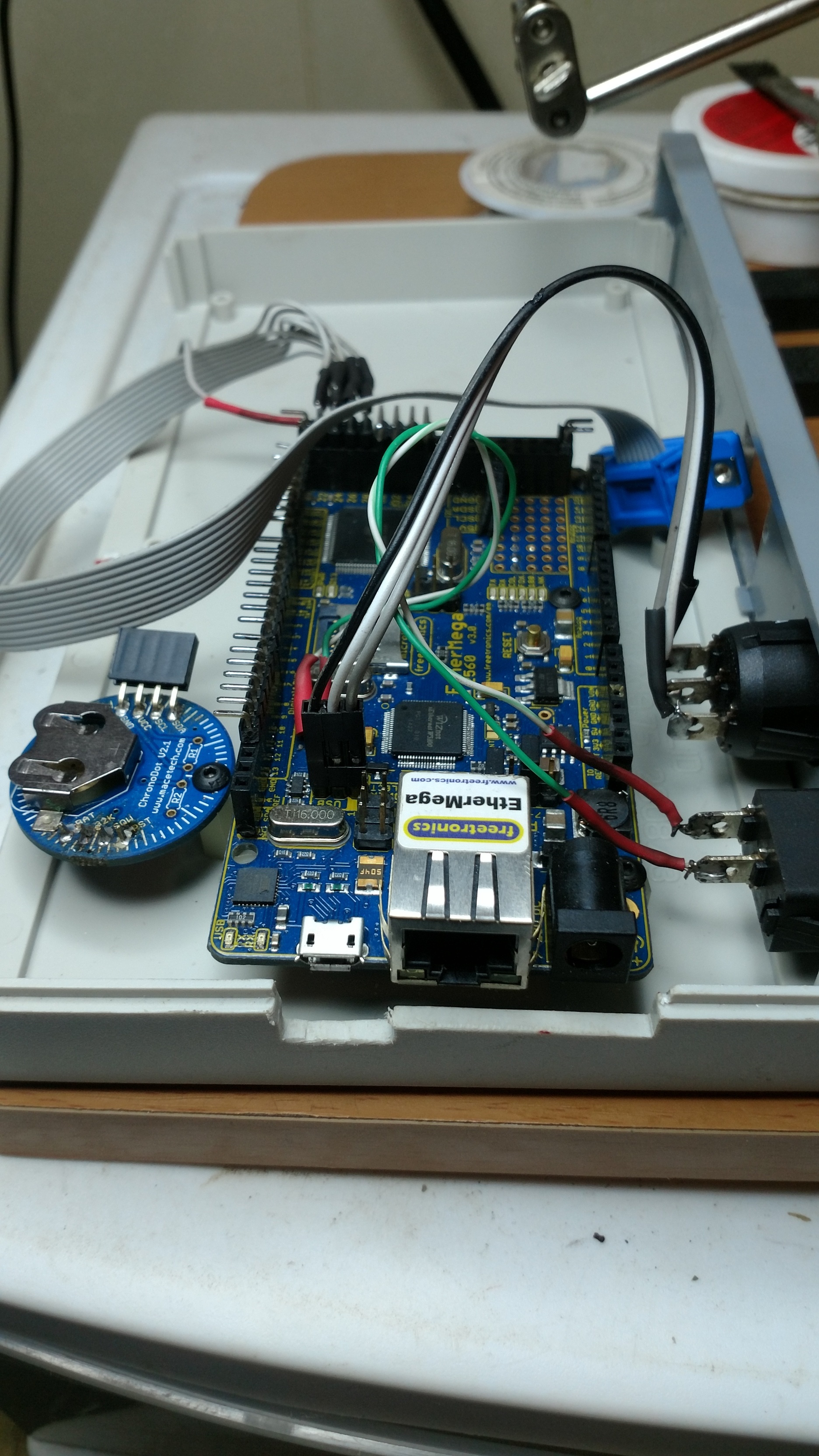
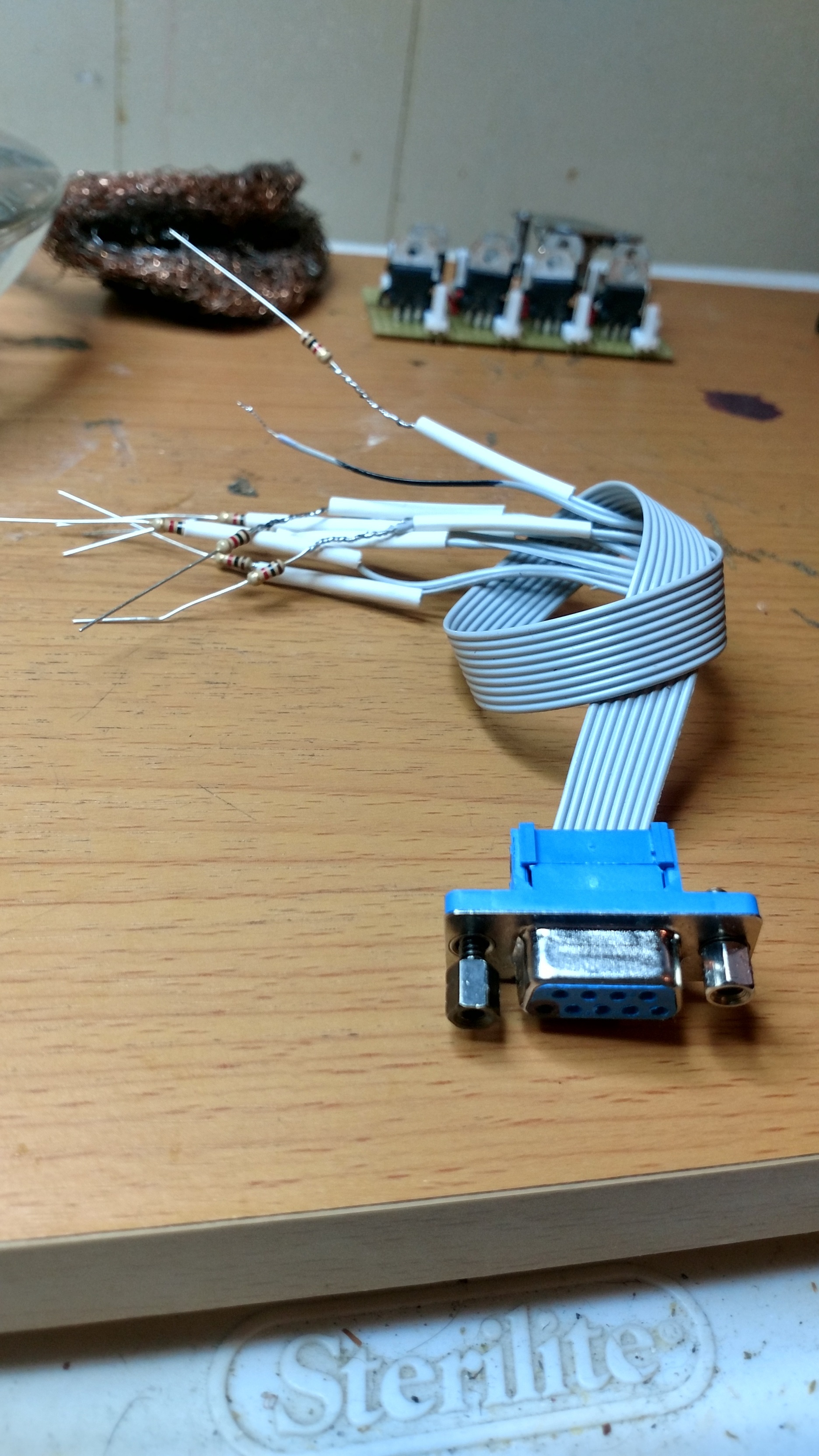
The pump housing consists of 2 (Jebao DP-4) dosing pump modules, a master and slave. My research on the subject lead me to a few aquarium forums and the general consensus on this brand/model was that it was fairly good for the price. I found the master for $80, and the slave for $65. Ironically, the master shipped from China and the slave from the USA, but this may be due to there being more complex circuits in the master, plus the 2A power supply. When shopping for some pumps, I knew immediately that it needed to be controlled by Arduino as that is what I use for my larger project. So more research for motor drivers returned a few different methods, but I eventually settled on a simple TIP120 circuit. It’s pretty well isolated, plus allows for PWM if I choose to later on. For now, I am using digital on/off for timed durations to produce the desired amount of fluids. Here is a LINK to a basic TIP120 circuit on the Arduino website. The only differences in my circuit and what is shared over there is that I use a 1k resistor between the Arduinos digital pins and the gate of each transistor. And instead of a dumb button on a breadboard I have Blynk!
Here is a YouTube video [Link] I shot this morning to demonstrate that the code that @Fettkeewl shared with me worked exactly how I wanted it to. The perspective is a screensharing app that also shoots video of the project in real time.
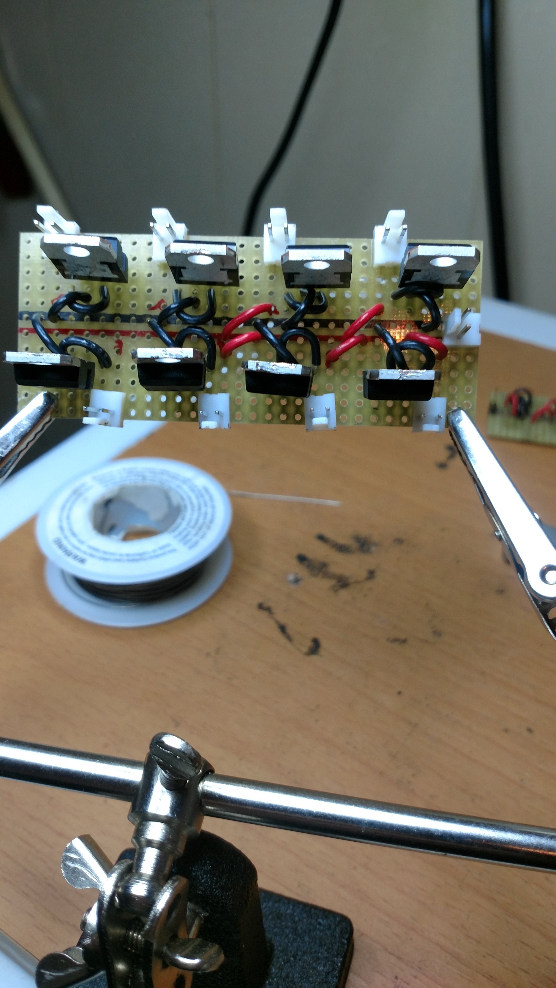
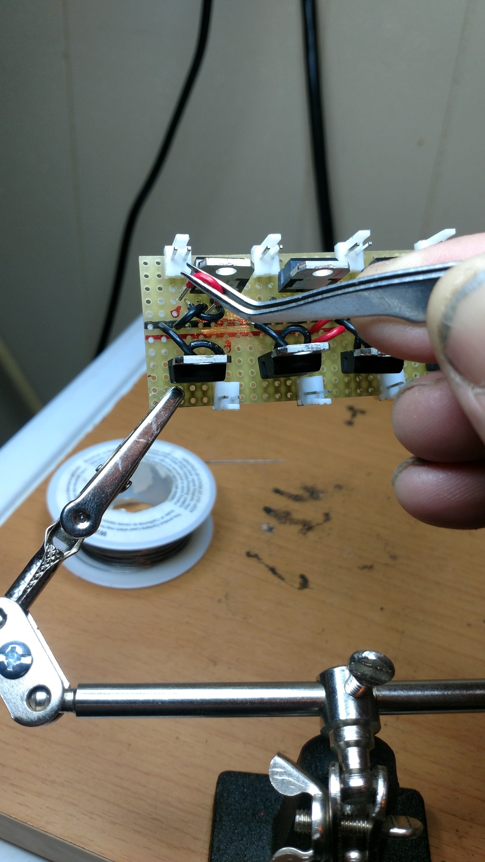
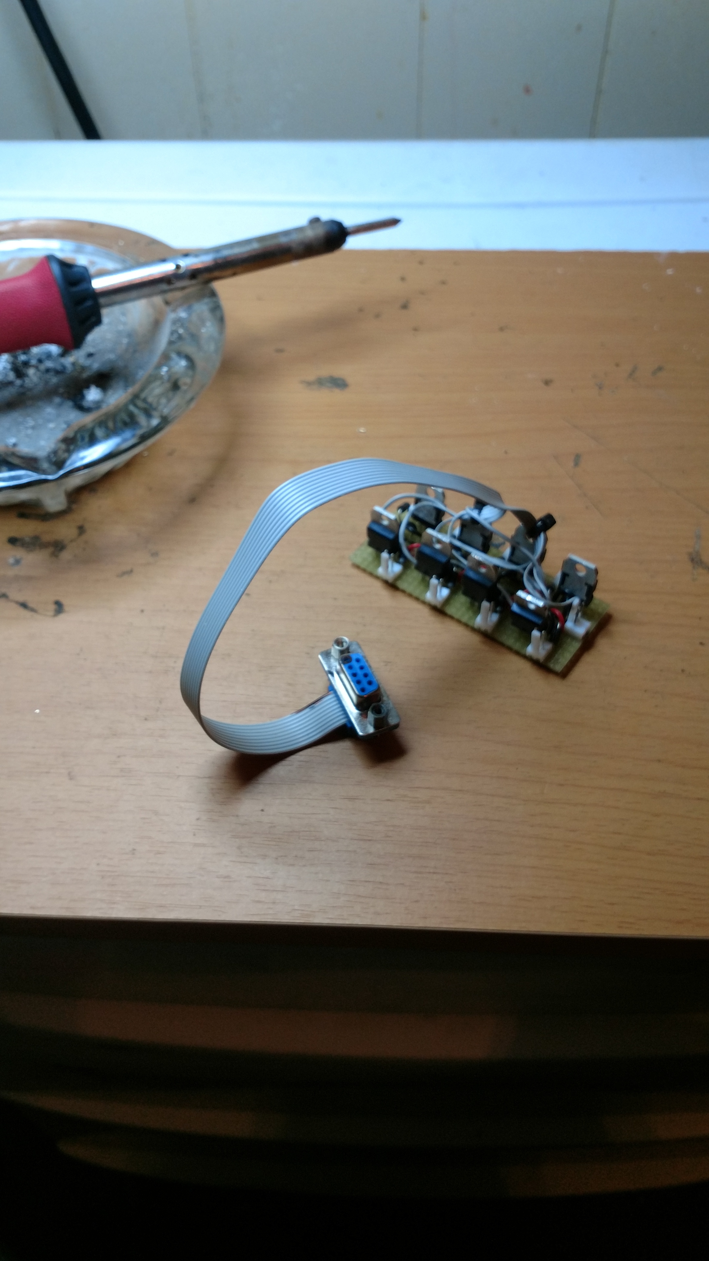
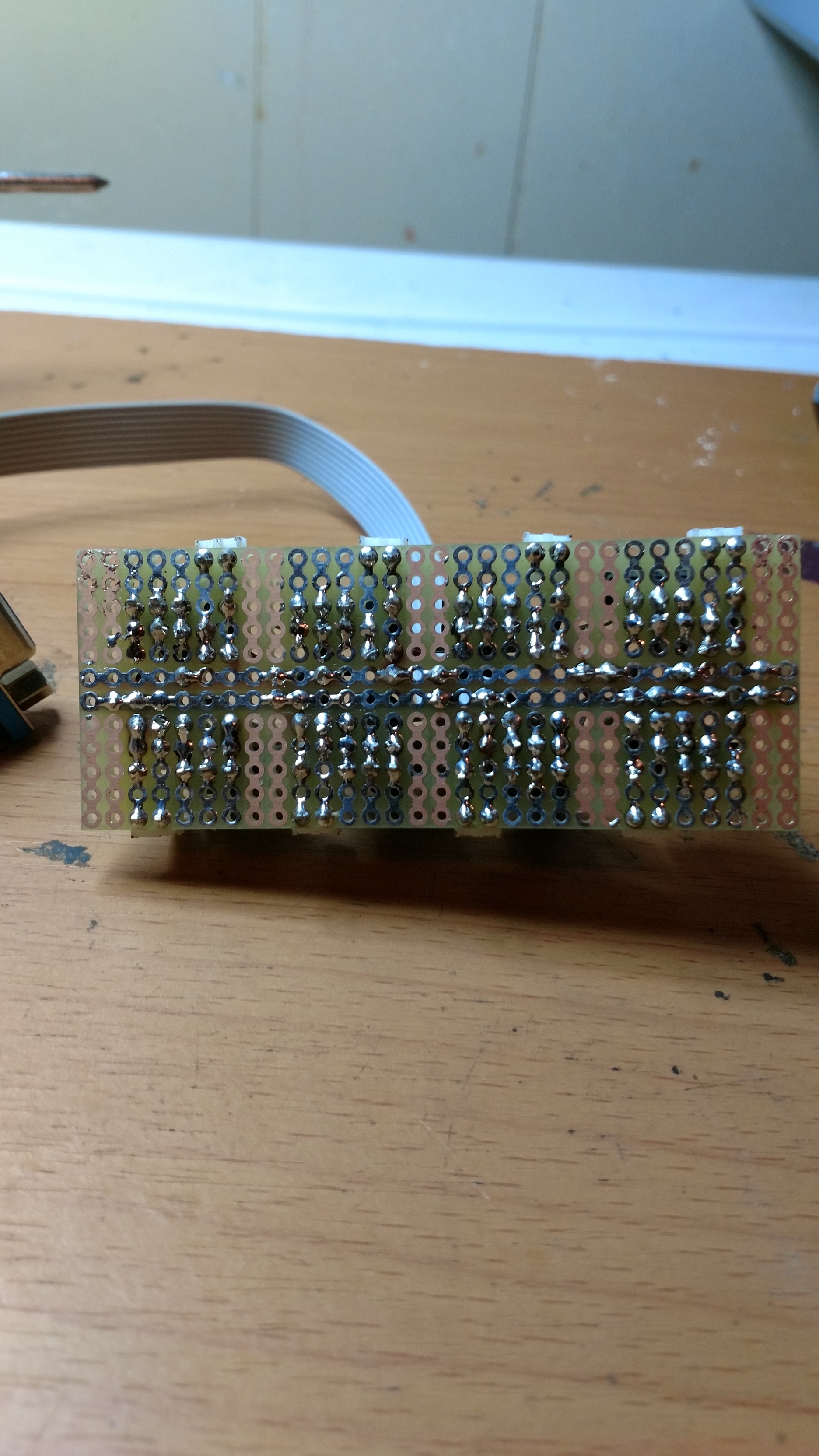
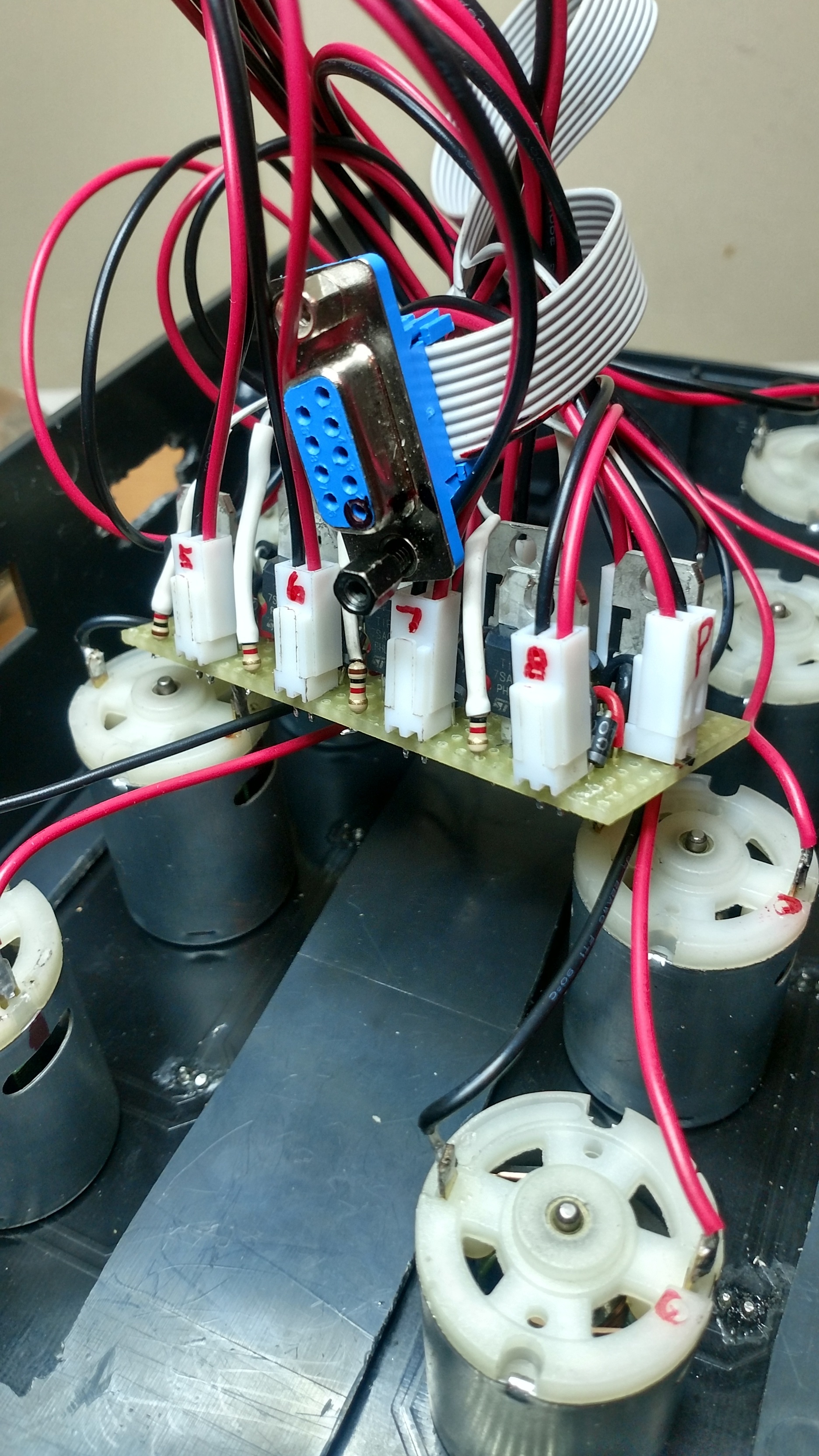
Here are some pics of the circuits that drive each motor. There are 8 total circuits comfortably situated on a solderable breadboard. I ruined two other breadboards previously, but I guess the third time is a charm.

Here is the calibration sketch that was gifted to me by a kind forum member on arduino.cc. The sketch does involve using a dumb button on a breadboard. I suppose the appropriate thing for me to do is nix the button and make it either a) work with Blynk as is, or b) readjust the project sketch to count millis while an app button is held HIGH and display it to the terminal widget. I predict this thread will be adjusted in about 2 weeks to a month! The purpose of a calibration sketch was to hold a pin HIGH while its motor turns the pump and pushes out liquid until 100ml of liquid is produced (visually in a beeker/measuring cup). Once 100ml is produced and the button is released, the output to the Serial Monitor is the amount of milliseconds that have elapsed while the button pin was held LOW. As the pin is normally held HIGH with INPUT_PULLUP, the LOW state activates the pump with analogWrite.
Perform this test at least 3 times per pump and record each millis output to find the average. Then divide the average by the amount of times the test was performed (3) and the quotient then becomes the Calibration Value that will be later used in the project sketch.
uint32_t start, eTime, dbStart;
const byte btn = 30, pumpPin = 2, dbTime = 20;
bool pinState = true,
     btnState = true,
     timing = false;
void setup()
{
  Serial.begin(9600);
  pinMode(btn, INPUT_PULLUP);
  pinMode(pumpPin, OUTPUT);
}

void loop()
{
  // debounce button ++++++++++++++++
  if (digitalRead(btn) != pinState) // get state of pin 30
  {
    dbStart = millis(); // reset db timer
    pinState ^= 1;      // now they are equal, won't enter
  }                     // here again unless pin state changes
  if (millis() - dbStart > dbTime) // db timer has elapsed
    btnState = pinState;           // button state is valid
  //+++++++++++++++++++++++++++++++++++
  if (btnState == LOW && !timing)
  {
    start = millis(); // start timing
    analogWrite(pumpPin, 255);
    timing = true;
    Serial.println(F("  Timing"));
  }
  if (btnState == HIGH && timing)
  {
    analogWrite(pumpPin, 0);
    eTime = (millis() - start);
    Serial.print(F("  Elapsed millis = "));
    Serial.println(eTime);
    timing = false;
  }

}
In the following sketch, the Calibration Value for each pump is grouped into an array called “multiplier” as it is to be multiplied by an additional value supplied by the Blynk app. This other value is the amount of milliliters I want a specific pump to produce. The way I wanted it was for this value to be a float so precise dosages could be achieved. The level of precision is setup in the app when you determine the value of each step of the Step Widget. For my larger project, 0.25ml increments are more than precise enough, but I can see how more precision may be desired so perhaps 0.1 per step, or even 0.01 per step? Just be mindful that when dialing up larger doses, it will take a considerable amount of time to increment or decrement through all of the steps. I suppose it’s a minor trade off!
To select a pump, another Step Widget is used, obviously with the step size being whole numbers, step = 1.0. This is an int BTW.
As it goes, I increment to the pump I want the values to apply to in the first Step Widget, I then in the second Step Widget increment to the amount of ml I want pumped, and once I’m happy with both, I tick the Button Widget and at the next iterance of the function in the Simple Timer, the motor spins (and pump produces). I know that once I deploy the project, I will need to recalibrate each pump, and likely by that time I would have already wrote or located the code needed to handle it with Blynk, but the viscosity of the fluid that will be assigned to each pump will DEFINITELY be very influential when determining the actual Calibration Value, at least we now have the code to adjust accordingly.
The sketch;
/*
eightPumps
*/
#include <SPI.h>                      //Used by Blynk
#include <Ethernet.h>                 //Used by Blynk
#include <BlynkSimpleEthernet.h>      //Used by Blynk
#include <SimpleTimer.h>
char auth[] = "PasteYourAuthCodeBetweenQuotes";       //Paste code that app emailed you between "quotes"

SimpleTimer timer;
WidgetTerminal terminal(V3);

int pumpPin[8] = { 2, 3, 4, 5, 6, 7, 8, 9 };         //Digital pins used
uint32_t multiplier[8] =  { 858, 827, 872, 865, 887, 895, 913, 843 }; //ms per ml
uint32_t startPump = 0;
uint32_t runCount;
float DOSEml;           //V1 Step Widget (0.25 per step, send step/NO, loop values ON)
int button = 0;         //V2 Button Widget set to Switch
bool pumpRunning = false;
int x;

BLYNK_WRITE(V0) {                 // Choose Pump
  x = param.asInt() - 1;
}
BLYNK_WRITE(V1) {                 // Adjust Dosage
  DOSEml = param.asFloat();
}
BLYNK_WRITE(V2) {                 // Activate Chosen Pump
  button = param.asInt();
}

void checkPump()
{

  if (button == 1 && pumpRunning == false)
  {
    Blynk.virtualWrite(V0, 0);
    Blynk.virtualWrite(V1, 0);
    Blynk.virtualWrite(V2, 0);
    pumpRunning = true;
    digitalWrite(pumpPin[x], HIGH);
    startPump = millis();
    runCount = DOSEml * multiplier[x];
    terminal.println("Dosing from Pump:");
    terminal.println(x + 1);
    terminal.println("Milliliters:");
    terminal.println(DOSEml);
    terminal.flush();
  }

  if (millis() - startPump > runCount)
  {
    digitalWrite(pumpPin[x], LOW);
    pumpRunning = false;
    button = 0;
  }

}

void setup()
{
  Serial.begin(9600);
  Blynk.begin(auth);
  while (Blynk.connect() == false) {}
  timer.setInterval(1500L, checkPump);
  for (int p = 0; p <= 7; p++)
  {
    pinMode(pumpPin[p], OUTPUT);
  }
  Blynk.virtualWrite(V0, 0);
  Blynk.virtualWrite(V1, 0);
  Blynk.virtualWrite(V2, 0);
}

void loop()
{
  Blynk.run();
  timer.run();
}