Blynkers.
My target ESP32 platforms of choice are Adafruit’s ESP32V2, with its high quality and Neopixel LED on the board, and Seeed Studio’s XIAO ESP32C6: tiny footprint, great with batteries.
This is not an advertisement, not a promotion, but an opportunity for me to return value to the Blynk community with an extremely useful product and my supporting code.
Seeed Studio’s XIAO 6-Channel Wi-Fi 5V DC Relay combines the XIAO ESP32C6 with 6 relays, indicator lights, and easy Blynk programmability in a surprisingly affordable package. I’ve built one project already with this product.
The six relays are heavy-duty, all completely isolated from each other and from the ESP32. The relays work with AC and DC and are rated to 15A at 120VAC. I am replacing a bunch of Shelly 1 switches with this, and may replace some Sonoffs, too. All in a nice compact package.
Here’s my almost-bare-bones Blynk code to demonstrate this device. Compiling to ESP32C6 and using default partitions, this sketch needs only your Blynk and WiFi credentials (in the two #include files) to demo this device.
There’s a screenshot at the end of my simple demo Blynk app. It’s just a demo.
I hope this is useful to someone in the Community.
Code: sketch with two #include files – one for WiFi credentials, the other for Blynk credentials. I have posted this on Github, will post more robust code soon.
All thoughts welcome.
Main sketch. (#include files to follow.)
// XIAO 6-Channel Relay Demo Sketch
// Seeed Studio https://www.seeedstudio.com/6-Channel-Wi-Fi-5V-DC-Relay-p-6373.html
// Seeed Studio https://www.seeedstudio.com/Seeed-Studio-XIAO-ESP32C6-p-5884.html

// Board: XIAO_ESP32C6
// PARTITION SCHEME: DEFAULT 4MB with spiffs


#define SERIAL_SPEED 230400   // My usual speed for Serial/development work
//#define SERIAL_SPEED 115200


#define BLYNK_FIRMWARE_VERSION "1.0.1"  //
#define PROGRAM_NAME_VERSION   "1-0-1"  // Dashes, not Dots


#define SKETCH_NAME "XIAO_Relay_v" PROGRAM_NAME_VERSION  // used in WiFi setup, Blynk and OTA
#define DEVICE_NAME "XIAO-Relay-v" PROGRAM_NAME_VERSION  // used in WiFi setup, Blynk and OTA


// ****************** XIAO 6-Channel Relay *****************
#include "MY_BLYNK_CREDENTIALS_DEMO.h"
#define BLYNK_TEMPLATE_ID          MY_XIAO_RELAY_TEMPLATE_ID        // FROM MY_BLYNK_CREDENTIALS.h
#define BLYNK_TEMPLATE_NAME        MY_XIAO_RELAY_TEMPLATE_NAME      // FROM MY_BLYNK_CREDENTIALS.h
#define MY_BLYNK_AUTHCODE          MY_XIAO_RELAY_DEVICE_AUTHCODE    // FROM MY_BLYNK_CREDENTIALS.h
// Added April 2026


#include "MY_WIFI_CREDENTIALS_DEMO.h"   // #defines MY_WIFI_SSID AND MY_WIFI_PASSWORD
#include "MY_BLYNK_COLORS.h"


// WiFi Stuff
#include "WiFi.h"                              // Now included from Espressif ESP32 3.0.0 Board package
#include <WiFiMulti.h>
WiFiMulti wifiMulti;                           // set up the WiFi object
const uint32_t connectTimeoutMs = 5000;        // timing for WiFiMulti testing connection


// Blynk Stuff
#include <BlynkSimpleEsp32.h>


////////////////////////////////////////////////////////////////////////////////////////////////////////
// Blynk Timers
// This sketch uses timers to kick off key processes
// See Pete Knight's doc at https://community.blynk.cc/t/using-blynktimer-or-simpletimer/53326

// Set up my standard timer here, before we bring in the Heartbeat
BlynkTimer myTimer;

/*  1 - Heartbeat (heartbeatBlink) - Interval Timer - simple pulse to show we're alive. May be switched off.
 *      Timer call turns heartbeat ON and prints diagnostics.
 *      It uses a second Duration timer to turn the heartbeat back OFF
 *  2 - Do something with the Switches every three seconds
 */

// ** timers get randomized in the code **

// Timer 1: Heartbeat LED and optional Blynk LED on and off
#define HEARTBEAT_INTERVAL 4250    // interval between heartbeats for Blynk Virtual LED in millisec
int heartbeatTimerID;              // HEARTBEAT_INTERVAL WILL BE RANDOMIZED +-500 ms (once at startup)

#define HEARTBEAT_DURATION 1250    // duration of each blink in millisec
int heartbeatDurationTimerID;      // (set as an interval timer once heartbeat is ON ... to turn it back OFF)


// Timer 2: Do something with the Switches every three seconds
#define TOGGLE_GPIO_INTERVAL 3 * 1000 // Do something every 3 seconds
int toggleGPIOtimerID;

// ***************************************************************************************************
////////////////////////////////////////////////////////////////////////////////////////////////////////
// End of Timers                                                                                      //
////////////////////////////////////////////////////////////////////////////////////////////////////////
////////////////////////////////////////////////////////////////////////////////////////////////////////


////////////////////////////////////////////////////////////////////////////////////////////////
////////////////////////////////////////////////////////////////////////////////////////////////
////////////////////////////////////////////////////////////////////////////////////////////////
////////////////////////////////////////////////////////////////////////////////////////////////
//
// Key Program Global Variables
//
////////////////////////////////////////////////////////////////////////////////////////////////

// Sets up HEARTBEAT widget, heartbeatBlink
#define HEARTBEAT_VPIN                      V0            // My standasrd Heartbeat VPIN
#define HEARTBEAT_LABEL                     "Working"
#define HEARTBEAT_COLOR                     BLYNK_LT_BLUE


bool heartbeatLEDon = false;    // this lets me use the same routine for the turn-on timer and the turn-off interval


// Sets up the 6 Switch Widgets
#define SWITCH_WIDGET_COLOR         BLYNK_BLACK
#define SWITCH_WIDGET_ON_COLOR      BLYNK_GREEN
#define SWITCH_WIDGET_OFF_COLOR     BLYNK_GREY

//// XIAO 6-CHannel Relay
// https://wiki.seeedstudio.com/6_channel_wifi_relay/
// https://www.seeedstudio.com/6-Channel-Wi-Fi-5V-DC-Relay-p-6373.html?srsltid=AfmBOoqth5qb8CrGU001aOXWS33ozvj0V8Ax3FVixJnjHNz0Us07LpExMR0

//  ||  Switch 1   GPIO2     GPIO18  Switch 6   /\
//  ||  Switch 2   GPIO21    GPIO19  Switch 5   ||
//  \/  Switch 3   GPIO1     GPIO00  Switch 4   ||

const int switchGPIO[6]    = { 02, 21, 01, 00, 19, 18 }; // GPIOs on the ESP32C6
const int switchVPIN[6]    = { 31, 32, 33, 34, 35, 36 }; // Blynk VPINs for the 6 Switch ON/OFF Widgets
bool currentSwitchState[6] = { false };                  // All OFF initially


//////////////////////////////////////////////////////////////////////////////////////////////////////////////////////
//////////////////////////////////////////////////////////////////////////////////////////////////////////////////////
//////////////////////////////////////////////////////////////////////////////////////////////////////////////////////
//////////////////////////////////////////////////////////////////////////////////////////////////////////////////////
//////////////////////////////////////////////////////////////////////////////////////////////////////////////////////
// SETUP WIFI, BLYNK, HEARTBEAT, AND 6 SWITCHES
//////////////////////////////////////////////////////////////////////////////////////////////////////////////////////
void setup()
{
  // Turn ON all Switches
  initializeAllSwitchGPIOs();         // Initialize to OFF
  allSwitchesONorOFF ( HIGH );  // Turn all 6 ON (before we try to connect to Serial)


  // Use a timer here for any OTA device, particularly the XIAO ESP32
  // CONTAINS DELAYS !!
  #define SERIAL_PRINT_DELAY 2500         // I use this delay for all ESP32s
  time_t serialWaitStartTime = millis();  // Protect against ESP32 hangup of no Serial Monitor available
  time_t serialWaitTime = 0;

  Serial.begin ( SERIAL_SPEED );

  while ( ( ! Serial ) && ( serialWaitTime < SERIAL_PRINT_DELAY ) )
  { /* wait for serial port to connect. Needed for native USB */
    serialWaitTime = millis() - serialWaitStartTime;
  }
  delay ( SERIAL_PRINT_DELAY - serialWaitTime );


  // Turn OFF all Switches
  allSwitchesONorOFF ( LOW );


  Serial.println ( "\n\n**********************************************" );
  Serial.println ( "Firing up " + String ( SKETCH_NAME ) );
  Serial.println();


  // Connect to WiFi and Blynk
  connectToWiFiAndBlynk();  // Connect to WiFi, then to Blynk server
  // calls initialzeBlynkWidgets from BLYNK_CONNECTED


  // Set Blynk Virtual Heartbeat LED OFF
  heartbeatLEDon = false;
  heartbeatBlink();            // start first heartbeat

  Blynk.virtualWrite ( HEARTBEAT_VPIN, 000 );


  // Blynk timers control heartbeat, status checking for ON/OFF vs schedule, etc.
  setupBlynkTimers();  // Establish Blynk timers after Blynk is connected


  Serial.println ( "\n**********************" );
  Serial.println (   "... Setup complete ..." );
  Serial.println (   "**********************\n" );

} // end setup


void loop()   // Standard void loop (no OTA for simplicity)
{
  Blynk.run();
  myTimer.run();

} // end loop


// SET UP BLYNK TIMERS FOR EVERYTHING
void setupBlynkTimers()
{
  Serial.println ( "\nSetting up Blynk timers" );


  // Introduce a little randomness to all times so they don't all sync up
  long randomizedInterval;


  // Timer 1: Heartbeat LED and optional Blynk LED on and off
  randomizedInterval = HEARTBEAT_INTERVAL + random ( -500, +500 );  // plus of minus half a second
  Serial.print ( "... heartbeat interval = " ); Serial.println ( randomizedInterval );
  heartbeatTimerID = myTimer.setInterval ( randomizedInterval, heartbeatBlink );


  // Timer 2: Do something with the Switches every three seconds
  Serial.print ( "... toggleGPIOtimerID = " ); Serial.println ( TOGGLE_GPIO_INTERVAL );
  toggleGPIOtimerID = myTimer.setInterval ( TOGGLE_GPIO_INTERVAL, randomlyChangeSwitchStates );


  Serial.println ( "... Blynk timers all set up.\n" );

} // end setupBlynkTimers


// BLYNK_CONNECTED GETS CALLED WHEN CONNECTING TO BLYNK SERVERS
// GETS CALLED IMMEDIATELY ON FIRST CONNECT TO BLYNK SERVER, TOO
BLYNK_CONNECTED()
{
  Serial.println ();
  Serial.println ( "*************************************************" );
  Serial.println ( "BLYNK_CONNECTED..." );
  Serial.println ( "*************************************************\n" );


  // Set up the Blynk App with all the static info (colors and labels)
  // Set up all the Blynk widgets
  initializeBlynkWidgets();

} // end BLYNK_CONNECTED


// Set up all Blynk widgets in the app includinng Heartbeat and Reboot
void initializeBlynkWidgets()
{
  Serial.println ( "Initializing all Blynk widgets" );


  // Set up heartbeat label and color
  Blynk.setProperty ( HEARTBEAT_VPIN, "label", HEARTBEAT_LABEL );
  Blynk.setProperty ( HEARTBEAT_VPIN, "color", HEARTBEAT_COLOR );


  // Set up the 6 Channel Switch Widgets
/*
const int switchGPIO[6]    = { 02, 21, 01, 00, 19, 18 }; // GPIOs on the ESP32C6
const int switchVPIN[6]    = { 31, 32, 33, 34, 35, 36 }; // Blynk VPINs
bool currentSwitchState[6] = { false };                  // All OFF initially

#define SWITCH_WIDGET_COLOR         BLYNK_BLACK
#define SWITCH_WIDGET_ON_COLOR      BLYNK_GREEN
#define SWITCH_WIDGET_OFF_COLOR     BLYNK_GREY
*/
  for ( int switchIndex = 0; switchIndex < 6; switchIndex++ ) // Switches numbered 1-6; Index goes from 0-5
  {
    Blynk.setProperty ( switchVPIN[switchIndex], "label",       "Switch " + String ( switchIndex + 1 ) );
    Blynk.setProperty ( switchVPIN[switchIndex], "color",       SWITCH_WIDGET_COLOR );
    Blynk.setProperty ( switchVPIN[switchIndex], "offColor",    SWITCH_WIDGET_OFF_COLOR );
    Blynk.setProperty ( switchVPIN[switchIndex], "onColor",     SWITCH_WIDGET_ON_COLOR );
  }

  allSwitchesONorOFF ( LOW );

} // end initializeBlynkWidgets


void initializeAllSwitchGPIOs() // Initialize all 6 GPIO relay controls to OUTPUT and turn OFF
{
  Serial.println( "Initializing All GPIOs to OFF" );

  for ( int switchIndex = 0; switchIndex < 6; switchIndex++ )
  {
    pinMode ( switchGPIO[switchIndex], OUTPUT );

    setSwitchState ( switchIndex, LOW );

    Serial.println ( "Initialized Switch " + String ( switchIndex + 1 ) + " at GPIO " + String ( switchGPIO[switchIndex]) + " and VPIN " + String ( switchVPIN[switchIndex] ) );
  }

  Serial.println();

} // end initializeAllSwitchGPIOs


void allSwitchesONorOFF ( bool newState )  // Turn all 6 switches ON or OFF
{

/*
const int switchGPIO[6]    = { 02, 21, 01, 00, 19, 18 }; // GPIOs on the ESP32C6
const int switchVPIN[6]    = { 31, 32, 33, 34, 35, 36 }; // Blynk VPINs
bool currentSwitchState[6] = { false };                  // All OFF initially
*/

  for ( int switchIndex = 0; switchIndex < 6; switchIndex++ )
  {
    setSwitchState ( switchIndex, newState );

    Serial.println ( "Changed Switch " + String ( switchIndex + 1 ) + " at GPIO " + String ( switchGPIO[switchIndex]) + " and VPIN " + String ( switchVPIN[switchIndex] ) + " to " + String ( newState)  );
  }

  Serial.println();

} // end allSwitchesONorOFF


BLYNK_WRITE_DEFAULT() // Using BLYNK_WRITE_DEFAULT to more easily handle 6 different switch inputs with same code
                      // Also allows keeping the VPINs in an array
{
  // THE VIRTUAL PIN THAT SENT THE MESSAGE TO BLYNK
  int writeVpin = request.pin;

  String message = "BLYNK_WRITE_DEFAULT called from VPin " + String ( writeVpin );

  Serial.println ( "\n\n" + message );


/*
const int switchGPIO[6]    = { 02, 21, 01, 00, 19, 18 }; // GPIOs on the ESP32C6
const int switchVPIN[6]    = { 31, 32, 33, 34, 35, 36 }; // Blynk VPINs
bool currentSwitchState[6] = { false };                  // All OFF initially
*/

  // See which switch - if any - just got changed
  for ( int switchIndex = 0; switchIndex < 6; switchIndex++ )
  {
    if ( writeVpin == switchVPIN[switchIndex] ) // Check which widget got hit
    {
      bool newSwitchState = param[0].asInt();

      Serial.println ( "User Hit Switch " + String ( switchIndex + 1 ) + ": " + String ( newSwitchState ) );

      if ( newSwitchState != currentSwitchState[switchIndex] )  // Change Switch State only if needed
      {
        setSwitchState ( switchIndex, newSwitchState );
      }

      else
      {
        // Do nothing
      }
      return;
    }
  }

} // end BLYNK_WRITE_DEFAULT


void randomlyChangeSwitchStates() // Randomly change switch states
{
  Serial.println ( "\nRandomly changing two Switches" );


  int randomSwitch = random ( 0, 6 );
  setSwitchState ( randomSwitch, LOW );


  randomSwitch = random ( 0, 6 );
  setSwitchState ( randomSwitch, HIGH );


  reportSwitchStates();

} // end randomlyChangeSwitchStates


void reportSwitchStates() // Read the 6 Switches and print out their GPIO states
{
  Serial.println();

  for ( int switchIndex = 0; switchIndex < 6; switchIndex++ )
  {
    int switchState = digitalRead ( switchGPIO[switchIndex] );

    Serial.println ( "Reading Switch " + String ( switchIndex + 1 ) + ": " + String ( switchState ) );

  }

} // end reportSwitchStates


void setSwitchState ( int switchIndex, bool newSwitchState )  // Set a Switch to a value
{
  digitalWrite ( switchGPIO[switchIndex], newSwitchState );

  Blynk.virtualWrite ( switchVPIN[switchIndex], newSwitchState );

  currentSwitchState[switchIndex] = newSwitchState;

} // end setSwitchState


// OPTIONAL Cutting down on the brightness of the Blynk LED Widget
#define BLYNK_LED_WIDGET_MAX_BRIGHTNESS 150         // Led Widget is [0-255]  150 = not very bright (from 255)

void heartbeatBlink()                               // Standard code (I usually put in an #include'd file)
{
  if ( heartbeatLEDon )                                             // LED is ON. Turn it OFF
  {
    Blynk.virtualWrite ( HEARTBEAT_VPIN, 000 );                     // Blynk LED off


    Serial.println ( " ..." );
  }

  else                                                              // LED is OFF. Turn it ON
  {
    // Turn LED_BUILTIN ON (via PWM) and Turn Blynk LED Widget ON
    Blynk.virtualWrite ( HEARTBEAT_VPIN, BLYNK_LED_WIDGET_MAX_BRIGHTNESS );       // BLynk LED on


    Serial.print ( "\n... heartbeat <" + String ( SKETCH_NAME ) + ">" );

    int wifiStatus = WiFi.status();
    if ( wifiStatus == WL_CONNECTED )
    {

      Serial.print ( " connected as " ); Serial.print ( WiFi.localIP() );
      Serial.print ( " to " + String ( WiFi.SSID() ) +
                  " at " + String ( WiFi.RSSI() ) + "dBm" );
    }

    else // not connected to WiFi
    {
      Serial.print ( " WiFi.status()=" );

      if ( wifiStatus <= 7 && wifiStatus >= 0 ) { Serial.print ( myWiFiStatus[wifiStatus] ); }
      else { Serial.print ( wifiStatus ); };
    }


    // Set a timer to turn off the heartbeat LEDs in a bit
    heartbeatDurationTimerID = myTimer.setTimeout ( HEARTBEAT_DURATION, heartbeatBlink );

  }

  heartbeatLEDon = ! heartbeatLEDon; // flip heartberat ON/OFF status

} // end heartbeatBlink


void connectToWiFiAndBlynk()  // My standard (simplified) WiFi connection code - usually in an #include file
{
  Serial.println();
  Serial.println ( "connectToWiFiAndBlynk called ..." );

  // Try to connect to WiFi, REBOOTS UNTIL IT WORKS.
  connectToWiFi();
  // Sets wifiOnline = true... or it reboots after 5-10 minutes


  Serial.println ( "Next, connect to Blynk. \n" );
  Blynk.config ( MY_BLYNK_AUTHCODE );
  Blynk.connect() ;


  // If Blynk is not connected, start the Blynk connect cycle
  if ( ! Blynk.connected() )
  {
    // Blynk is NOT online
    Serial.println();
    Serial.println ( "connectToWiFiAndBlynk INITIALLY CANNOT connect to Blynk" );
    Serial.println();

    ESP.restart();

  } // Blynk is offline


  else
  {
    Serial.println ( "... Blynk connected up nicely\n" );
  }

} // end connectToWiFiAndBlynk


// Global variable indicating WiFi Online
#define WIFI_INITIAL_CONNECT_DURATION 1500          // Wait 1.5 seconds between WiFi.begin and first test for connectivity
#define WIFI_RETRY_CONNECT_INTERVAL   10L * 1000L   // 10 seconds between WiFi connect retries
#define WIFI_RETRIES_BEFORE_REBOOTING 5

void connectToWiFi()    // Connect to WiFi. Reboot on repeated failure
{
  WiFi.persistent ( false ); // Don't save anything in EEPROM or LittleFS
  WiFi.mode ( WIFI_STA );    // Station mode


  // Count the number of WiFi connection retries
  int WiFiTries = 0;


///////////////////////////////////////////////////////////////////////////////////////////////////////
///////////////////////////////////////////////////////////////////////////////////////////////////////

  Serial.println ( "******************* connectToWifi using Static SSID/Pswd *****************" );
  Serial.println ( "******************* connectToWifi using Static SSID/Pswd *****************" );


  // Register THREE multi WiFi networks
  wifiMulti.addAP ( MY_WIFI_SSID,  MY_WIFI_PASSWORD  );
  wifiMulti.addAP ( MY_WIFI_SSID2, MY_WIFI_PASSWORD2 );
  if ( MY_WIFI_SSID3 != "" ) wifiMulti.addAP ( MY_WIFI_SSID3, MY_WIFI_PASSWORD3 );


  // Test for WiFi connectivity. Reboot after 5 tries.
  while ( wifiMulti.run ( connectTimeoutMs ) != WL_CONNECTED )
  {
    WiFiTries++;

    Serial.print ( "WiFi not connected... #" ); Serial.println ( WiFiTries );

    if ( WiFiTries >= WIFI_RETRIES_BEFORE_REBOOTING  )
    {
      Serial.println ( "RESTARTING!  Cannot connect to WiFi\n\n" );

      delay ( 5000 );
      ESP.restart();
    }

    delay ( WIFI_RETRY_CONNECT_INTERVAL ); // This delay is ok for OTA and Blynk prior to WiFi connection
  }

  // Tell the world we are connected to WiFi
  Serial.print ( "WiFi connected on attempt #" + String ( WiFiTries + 1 ) + " just fine to ");
  Serial.print ( WiFi.SSID() ); Serial.print ( " at " ); Serial.println ( WiFi.localIP() ); Serial.println();
  Serial.println();

} // end connectToWiFi
End of Code.
Now, the #include files
I use #include files to keep my Blynk and WiFi credentials out of my code. Here are two examples for the XIAO code, above:
#include "MY_WIFI_CREDENTIALS_DEMO.h" // #defines MY_WIFI_SSID AND MY_WIFI_PASSWORD
// #include "MY_WIFI_CREDENTIALS.h"   // #defines MY_WIFI_SSID AND MY_WIFI_PASSWORD


#define MY_WIFI_SSID      "myPrimarySSID"                // network SSID (name)
#define MY_WIFI_PASSWORD  "myPassword"                   // network password

// Use as a backup SSID if #1 fails so I can use my phone to reconnect, reprogram when needed
#define MY_WIFI_SSID2     "myNextSSID"                   // network SSID (name)
#define MY_WIFI_PASSWORD2 "AnotherPSWD"                  // network password

//  Can add a 3rd SSID and password here... (but must have 3 in total)
#define MY_WIFI_SSID3      ""                            // network SSID (name)
#define MY_WIFI_PASSWORD3  "passowordo"                  // network password


// for diagnostic and heartbeat use
// WiFi.status ( return codes )
const char *myWiFiStatus[8] = { "0-WL_IDLE_STATUS", "1-WL_NO_SSID_AVAIL",  "2-UNKNOWN",
  /* for use in heartbeat*/     "3-WL_CONNECTED",   "4-WL_CONNECT_FAILED", "5-UNKNOWN",
                                "6-WL_CONNECT_WRONG_PASSWORD",
                                "7-WL_DISCONNECTED" };
/*
0 : WL_IDLE_STATUS when Wi-Fi is in process of changing between statuses
1 : WL_NO_SSID_AVAILin case configured SSID cannot be reached
3 : WL_CONNECTED after successful connection is established
4 : WL_CONNECT_FAILED if connection failed
6 : WL_CONNECT_WRONG_PASSWORD if password is incorrect
7 : WL_DISCONNECTED if module is not configured in station mode

Useful commands
WiFi.printdiag ( Serial ); lots of stuff, (not RSSI)
*/
#include "MY_BLYNK_CREDENTIALS_DEMO.h"
//#include "MY_BLYNK_CREDENTIALS.h"  // #defines MY_BLYNK_SERVER and MY_xxx_AUTHCODE

#define MY_BLYNK_SERVER                            "blynk.cloud"                  // Common to all New Blynk sketches

#ifndef BLYNK_FIRMWARE_VERSION
  #define BLYNK_FIRMWARE_VERSION                     "1.2.3"
#endif

//#define BLYNK_USE_128_VPINS true // Gives codes for VPINS up to V127


//////////////////////////////////////////////////////////////////////////////
//////////////////////////////////////////////////////////////////////////////
  // These are dummy Template IDs and Device Authcode for the XIAO demonstration
//////////////////////////////////////////////////////////////////////////////
//////////////////////////////////////////////////////////////////////////////


// ****************** XIAO 6-Channel Relay *****************
// 6 //
#define MY_XIAO_RELAY_TEMPLATE_ID                   "TMPL2aaaaaaaa" // Use YOUR credentials
#define MY_XIAO_RELAY_TEMPLATE_NAME                 "XIAO Relay Template"
#define MY_XIAO_RELAY_DEVICE_AUTHCODE               "yyyyyyyyyyyyyyyyyyyyyyyyyyyyyyyy"
// ADDED June 2026


// ************** DUMMY TEMPLATE **************
// 99 //
// THESE ARE DUMMY SETTINGS FOR MY STARTUP TEMPLATE IN EXAMPLES
#define MY_STARTUP_TEMPLATE_ID                      "XXXXXXXXXXXX"                // My Blynk Startup Template in Examples
#define MY_STARTUP_TEMPLATE_NAME                    "Startup Template"
#define MY_STARTUP_DEVICE_AUTHCODE                  "yyyyyyyyyyyyyyyyyyyyyyyyyyyyyyyy"
Screenshot of a very simple Blynk app
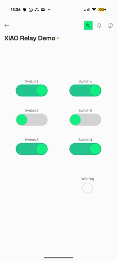
Again, I hope this is useful.