Hi
Files are here (fritzing breadboard sketch and code also below)
I’m a relative newby, and have embarked on a project for my dad to use on his Farm. I have no doubt I haven’t done things perfectly (and possibly even some things wrong) so I thought I’d share my project and see if anyone has any improvements.
Background: we’ve just installed a bore pump which has a pressure switch to turn itself off once the tank it pumps into is full and the inlet float valve closes. As our tank overflows into a dam he doesn’t want to install the float valve.
Instead, taking advantage of the pipe running straight past the house I decided to put a Solenoid valve controlled via a nodemcu. Although just within the wifi signal of the house, we didn’t want to run power out to the valve and hence has been designed to run off solar/battery. Because of this we changed out the usual 24vac solenoid with a 12vdc latching solenoid (pulse required to open valve and reverse polarity pulse required to close. I.e no constant power required to keep valve open).
Specifics:
Solar Panel
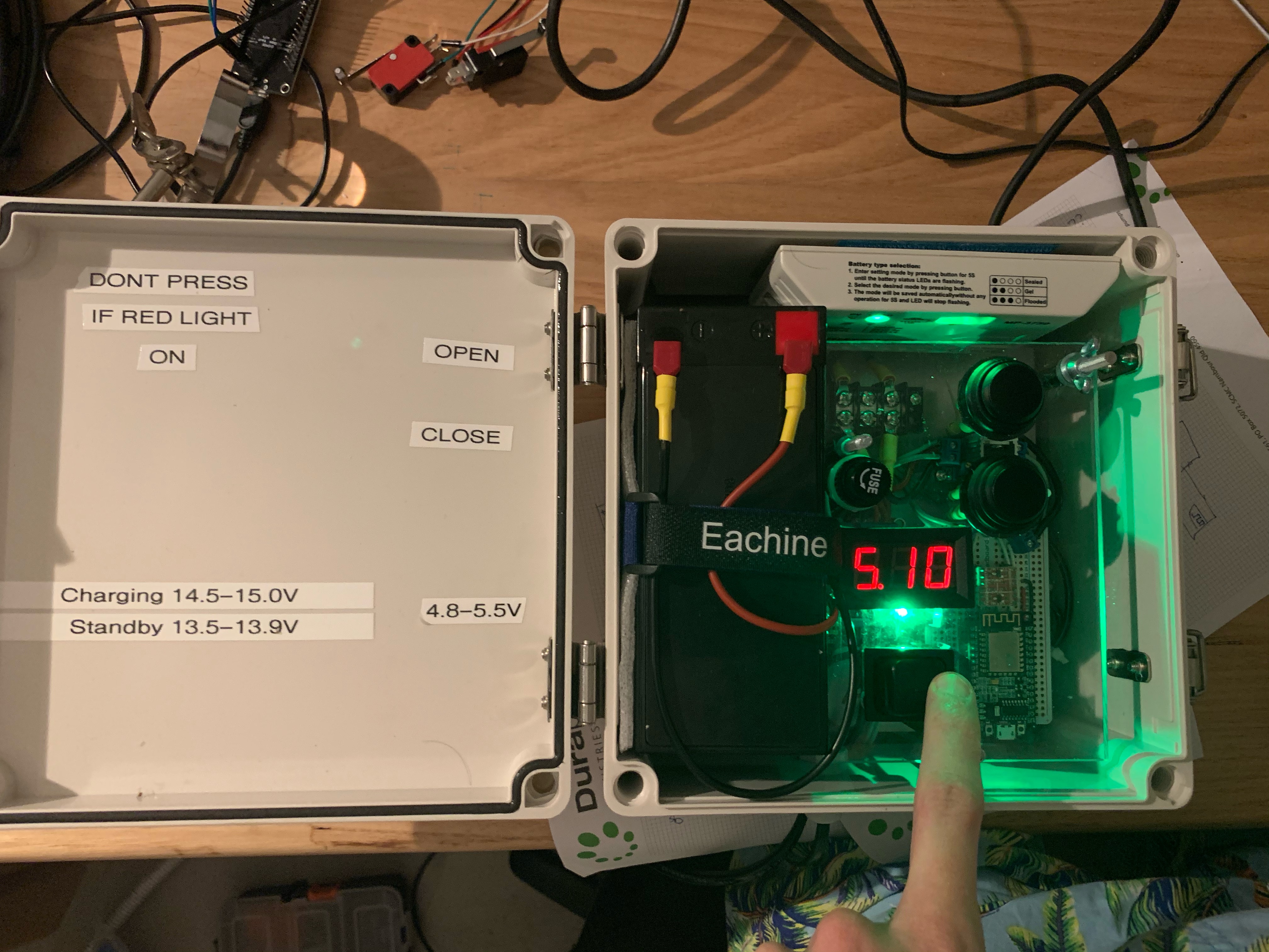
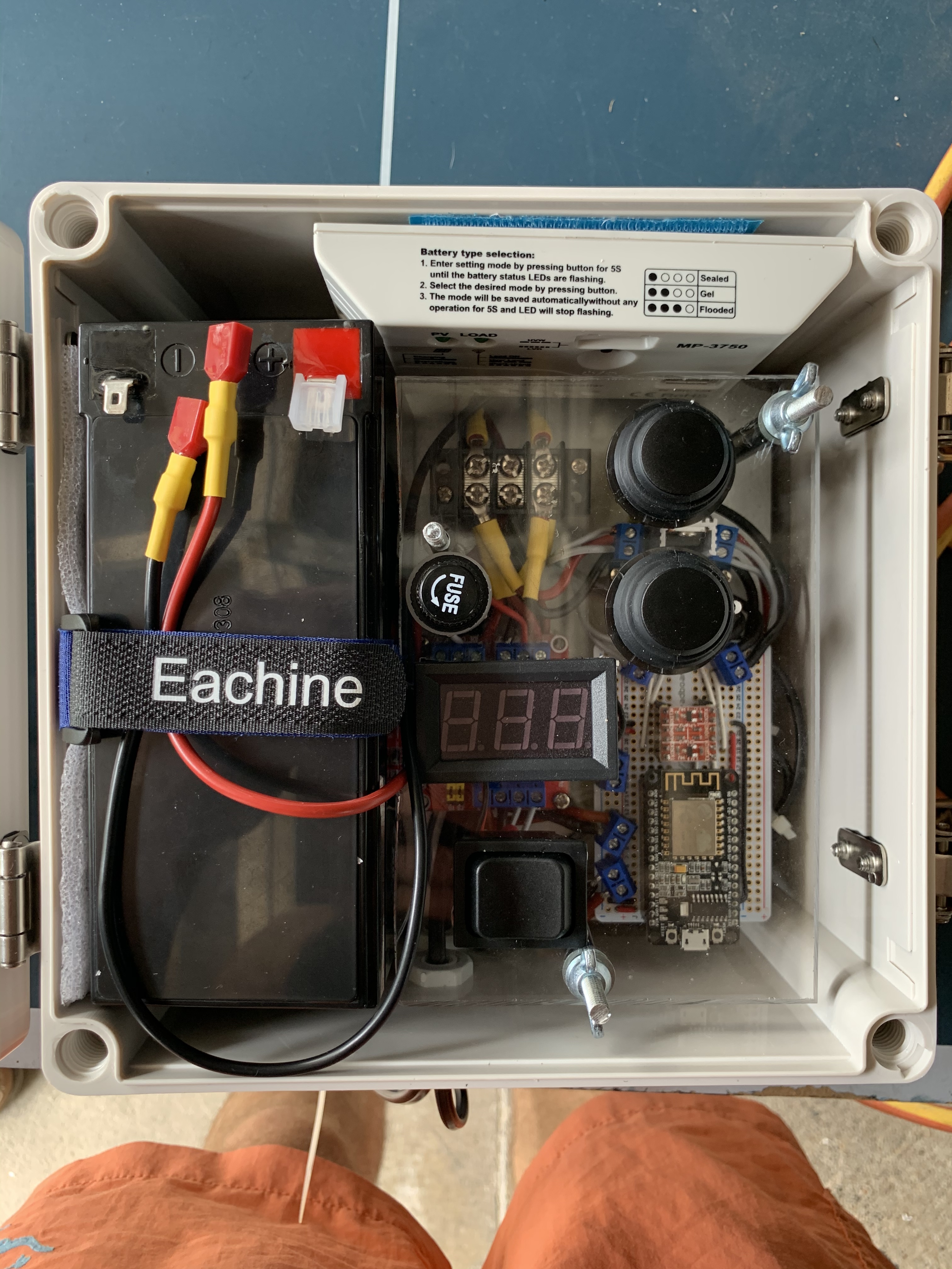
6ah SLA battery
Solar controller
12v adjustable buck step down (to 5V)
5V 2 channel relay board with selectable low/high activate. I’ve gone with LOW to activate relay. The two relays are wired to reverse the polarity for open/close commands.
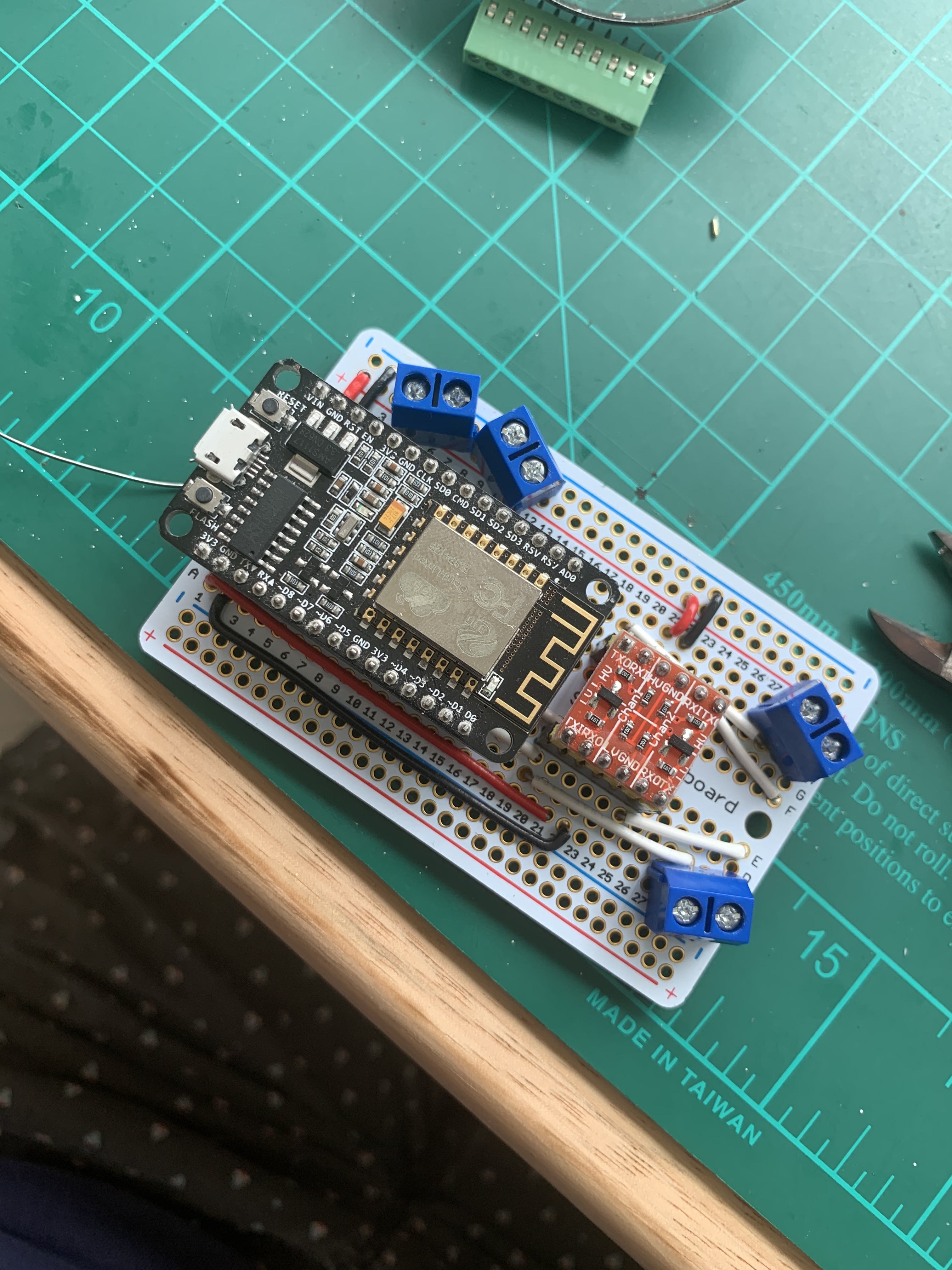
Nodemcu
Logic Level converter (to interface from 3.3v nodemcu to the 5V relay board)
https://www.jaycar.com.au/arduino-compatible-logic-level-converter-module/p/XC4486
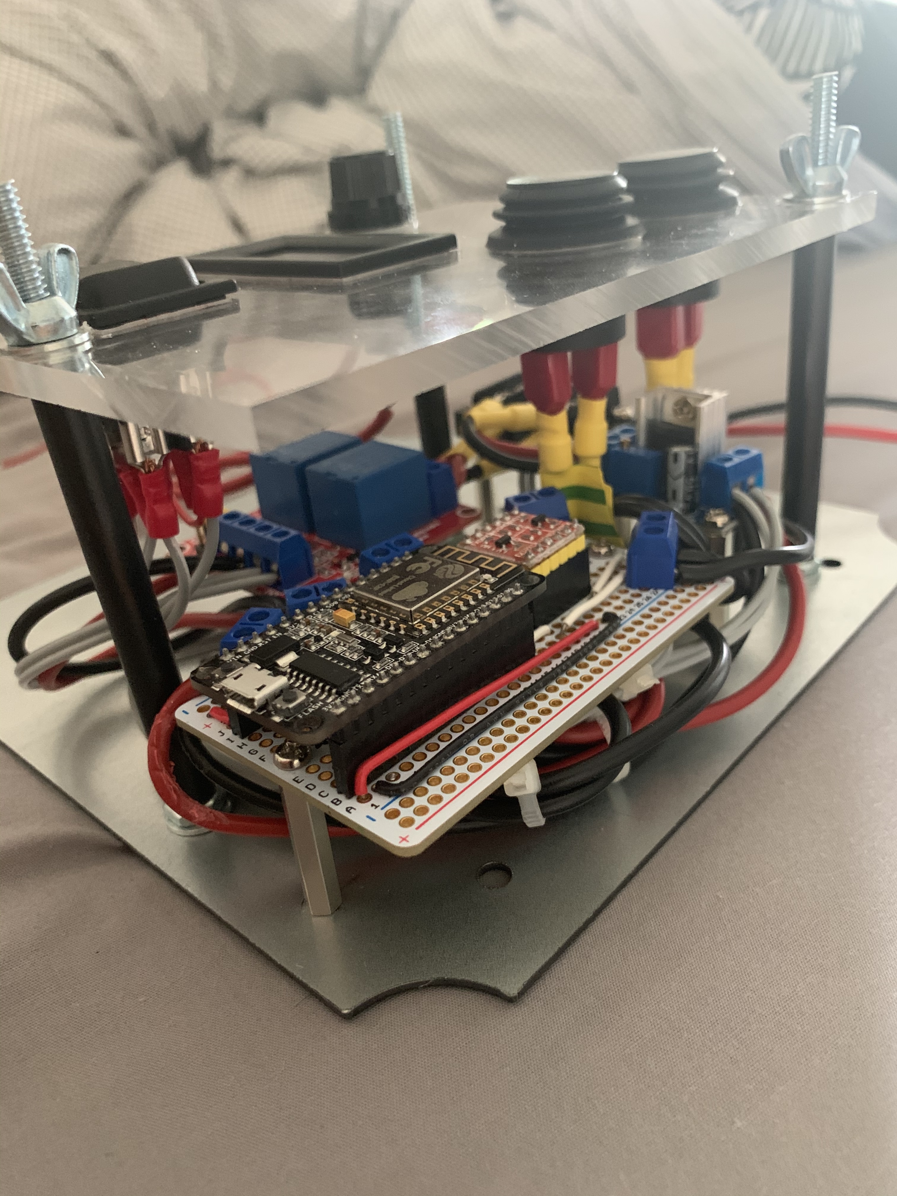
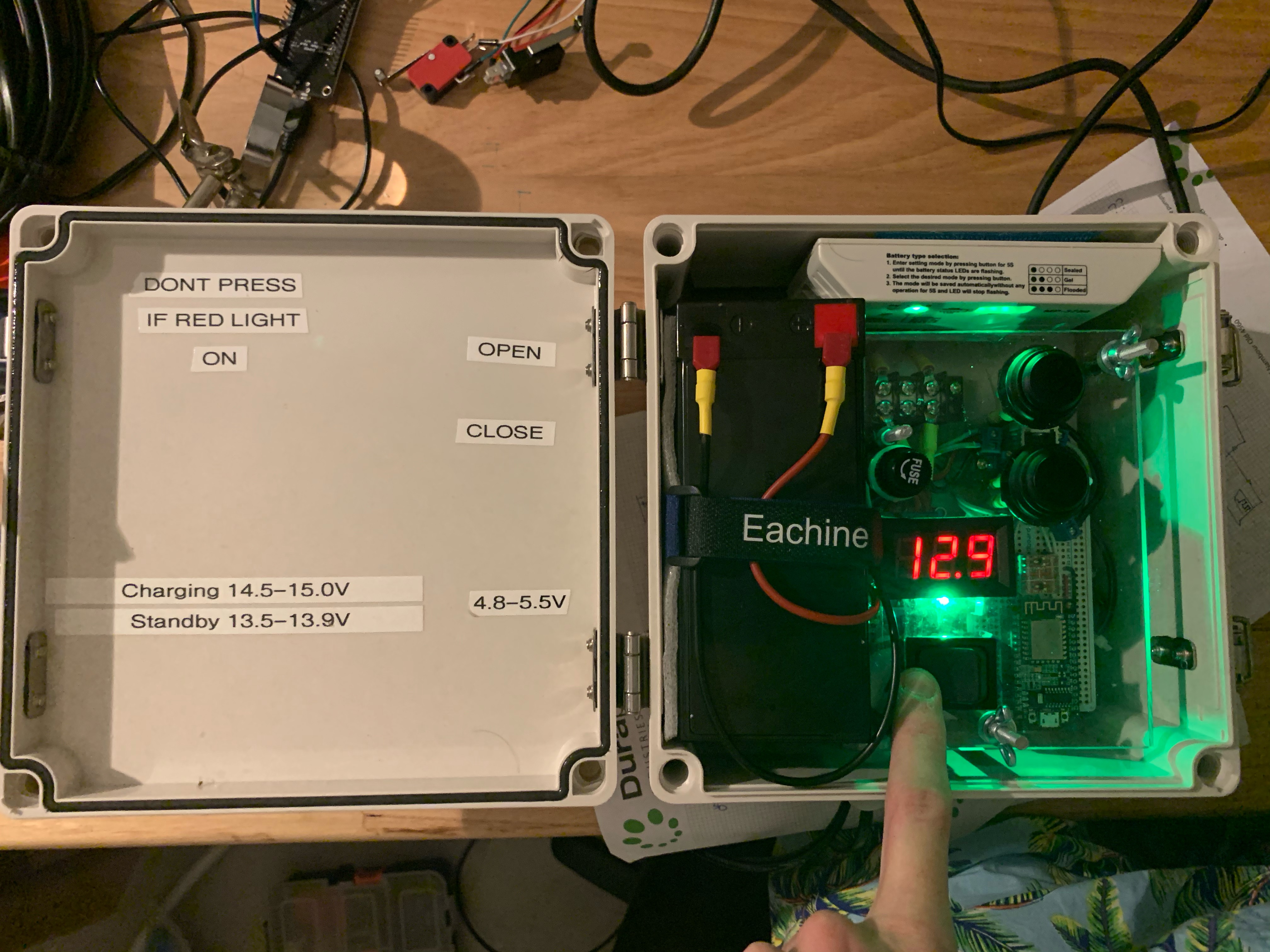
Additionally I added the following for local control and monitoring:
- 2 x momentary switches to open/close valve if wifi is down (by grounding the signal line to LLC and hence relay board)
- LCD Voltmeter connected through a centre off momentary dpdt switch to either side of the step down voltage regulator. (to check voltages both sides of the step down, but only when at the panel to avoid unnecessary current draw. I believe I could just used a spdt switch and used a common ground for this but i had the dpdt lying around.l)
Fairly simple Blynk setup. Two virtual pins (V10, V11) attached to the Open and closed button pins on Nodemcu. Also chucked in a wifi signal setproperty as the install will be right on edge of the wifi range.
A couple of specific questions.
-
For setup and testing I’ve been using a constant 12.4V supply from wall wart. When I deploy and connect to Solar/battery obviously the input voltage will range based on how sunny it is and how much we’ve drained from battery. Will this effect the 5V output of the step down, and hence cause issues for the Nodemcu and relay board both powered off the 5V?
-
The physical buttons are just a direct connections between signal circuit to ground. So when physical button is pressed although the Nodemcu is default HIGH the physical button grounds the signal line to LLC and then relay board. Although functionally this is working I’d like some feedback on whether this is good/best practice.
-
I havent quite got my head around pull-up/pull-down resistors. Being good practice I have pulled up the D1 Output pin to 5V. Do I need to, or is this done on the board itself?
Any questions/comments would be greatly appreciated as this project has given me a good feel for what is possible.
//To Control Irrigation Solenoid valuve at Farm

//Open button (V10) and close button (V11) to trigger relays forcing solednoid valve to open/close

#define BLYNK_PRINT Serial
#include <ESP8266WiFi.h>
#include <BlynkSimpleEsp8266.h>

char auth[] = "xxxx";
char ssid[] = "xxxx";
char pass[] = "xxxx";

BlynkTimer timer;

int value;
int relaypin1 = 4;  // digital pin for relay 1
int relaypin2 = 5;  // digital pin for relay 2
String displaywifi;
int wifisignal;

void setup()
{
  // Debug console
  Serial.begin(115200);
  digitalWrite(relaypin1, HIGH);
  digitalWrite(relaypin2,HIGH);
  pinMode(relaypin1,OUTPUT);
  pinMode(relaypin2,OUTPUT);

  Blynk.begin(auth, ssid, pass);

  timer.setInterval(1000000L, sendwifi);

}

BLYNK_WRITE(V10)
{
  value = param.asInt(); // Get State of Virtual Button

  Serial.print("V10 button value is: ");
  Serial.println(value);

  if (value ==1){
    digitalWrite(relaypin1,LOW);
  }
  else{
    digitalWrite(relaypin1, HIGH);
  }
}

BLYNK_WRITE(V11)
{
  value = param.asInt(); // Get State of Virtual Button

  Serial.print("V10 button value is: ");
  Serial.println(value);

  if (value ==1){
    digitalWrite(relaypin2, LOW);
  }
  else{
    digitalWrite(relaypin2,HIGH);
  }
}

void loop()
{
  Blynk.run();
  timer.run();
}
void sendwifi()
{
  wifisignal = map(WiFi.RSSI(), -105, -40, 0, 100);
  displaywifi = String("           Wifi: ") + wifisignal +String("%");

  Blynk.setProperty(V10, "label", displaywifi);
  Blynk.setProperty(V11, "label", displaywifi);

}

BLYNK_APP_CONNECTED(){
  Blynk.syncAll();

}

